Global Power Technologies MAINTENANCE
302842 Rev0 | Sentinel Page 41 of 61
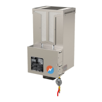
5.4 CATALYTIC CARTRIDGE ASSEMBLY REPLACEMENT
Figure 27 – Replacing the Catalytic Heater Cartridge
Replace the catalytic heater cartridge on the interval determined from Section 5.1.2:
1. Ensure the heater cartridge has been allowed to cool (~20 minutes) prior to handling.
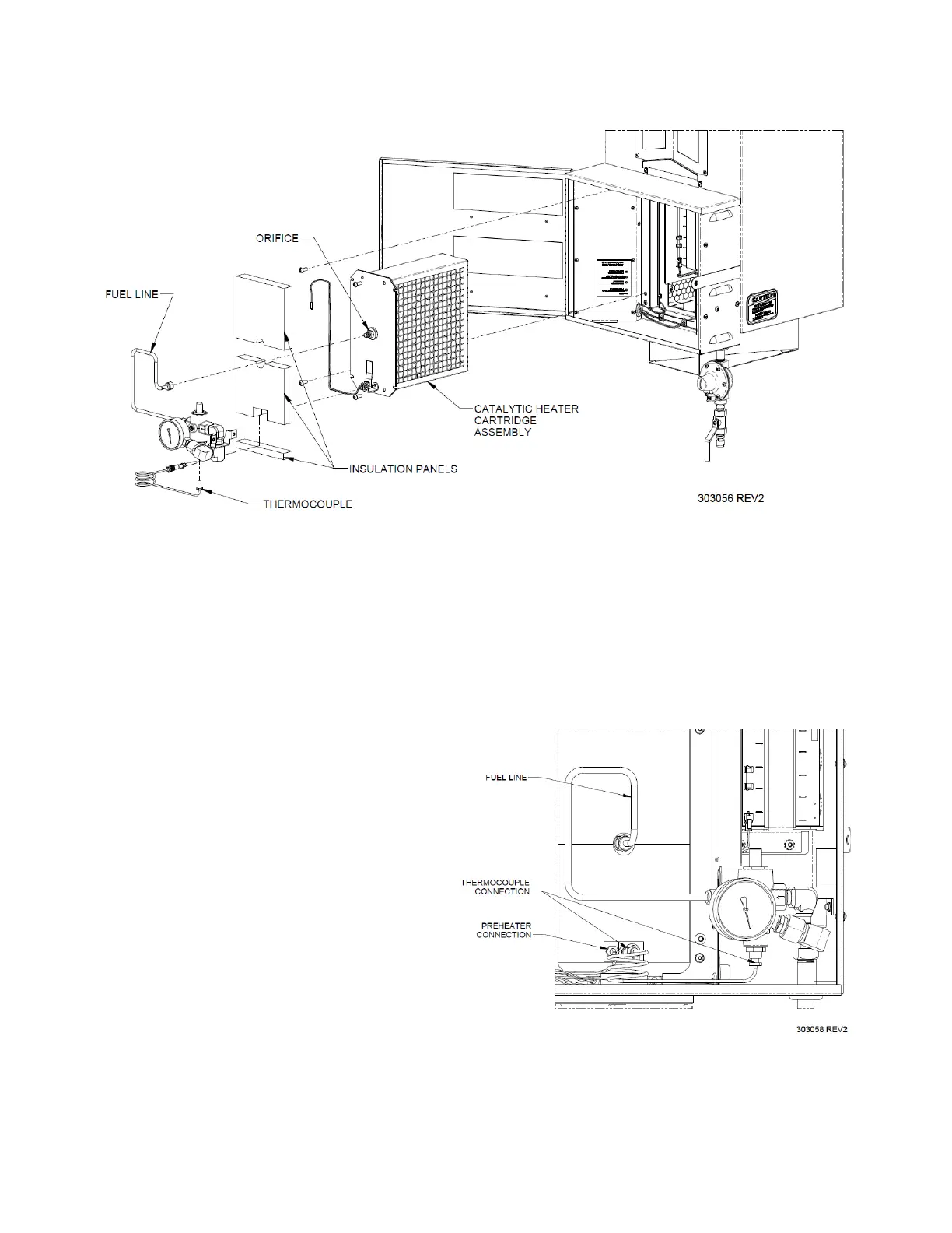
2. Unplug the ‘PREHEATER’ wiring connection from the top of the main circuit board. Remove cable ties
as necessary, then route the preheater wires back outside of the electronics enclosure.
3. Remove the three insulation panels from the center of the instrumentation enclosure to access the
catalytic heater cartridge assembly chamber.
4. Disconnect the fuel line from the orifice in
the center of the catalytic heater assembly
face and the elbow connector on the safety
shut-off valve. Save this for re-installation.
5. Disconnect the thermocouple from the
bottom of the catalytic heater assembly face
and the bottom of the safety shut-off valve.
Save this for re-installation.
6. Remove the four screws securing the
catalytic cartridge assembly using a 3/32”
hex key.
7. Pull the catalytic heater cartridge assembly
out of the catalytic heater chamber.
8. Insert a new catalytic heater cartridge into
the catalytic heater chamber, positioned
with the two holes on the bottom.
9. Secure the new cartridge using the four #8-32 x 3/8" screws that were previously removed.
Figure 28 – Catalytic Heater Connections
 Loading...