0020167175_01 - 02/13 - Glow-worm
10.2 Main board
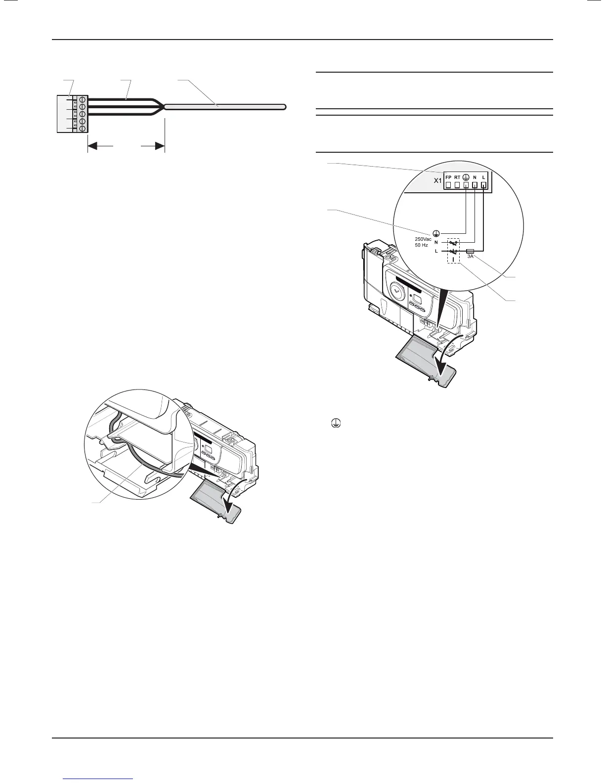
1 2 3
30mm
max
Key
1 Connector
2 Electrical wires
3 Insulation
• Keep a distance of a maximum of 30 mm between connector
(1) and the start of the insulation (3).
• Fix the cables in the cable-clamp on the eBox.
10.3 Electrical wiring
Connection of the whole electrical system and any heating system
controls to the electrical supply must be through a double poled
common switched and fused isolator.
The isolator shall have a contact separation of 3mm on each pole.
It should be identifi ed as to its use. Wiring to the boiler must be
PVC 850C insulated cable not less than 0.75mm² (24/0.20).
A fused three pin plug and shuttered socket outlet may be used
instead of a fused spur box provided that it is not used in a room
containing a fi xed bath or shower.
24
V
1
Key
1 Power supply cable
• Connect the appliance's power cable to the 230 V single-phase
network + earth.
• Observe correct polarity when connecting the appliance.
10.3.1 230V permanent supply
a
DANGER:
All cables connected to the appliance should be
permanently fi xed to the wall.
i
IMPORTANT:
This appliance will not operate without a link or system
controls fi tted.
24
V
3
4
1
2
Key
1 230V permanent supply
2 Main board terminal block
= Mains earth
N = Mains neutral
L = Mains live
3 Fuse
4 Double pole connector
• Connect mains supply as described.
INSTALLATION
- 18 -
 Loading...
