0020167175_01 - 02/13 - Glow-worm
11 Commissioning
i
IMPORTANT:
At the time of commissioning, complete all relevant
sections of the Benchmark Checklist located in the centre
pages of this document.
The commissioning should be carried out by a competent person
approved at the time by the Health and Safety Executive and in
accordance with the current issue of BS6798.
11.1 Reading the fi lling pressure
The boiler is equipped with an analogue pressure gauge.
The pressure guage is located behind the front panel of the
boiler on the fl ow pipe. The guage is intended to be used as an
installation aid, the guage is not intended to be used by the
customer.
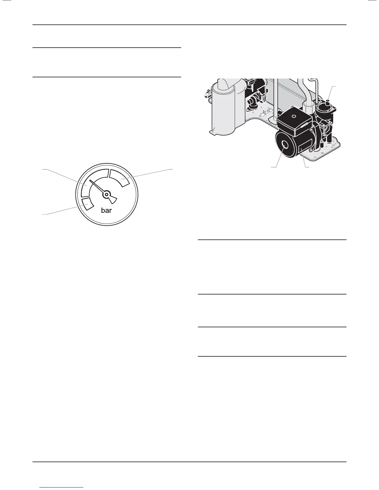
2
1
3
Key
1 White area, pressure too low
2 Grey area, normal operating pressure
3 Red area, pressure too high
To ensure the correct operation of the heating installation, the
indicator on the pressure gauge should be within the grey area
(2) in approximately the central position as shown in the diagram.
This corresponds to a fi lling pressure of between 0.1 MPa and 0.2
MPa (1.0 bar and 2.0 bar).
11.2 Switching on
• Do not operate the boiler without water.
• Make sure that the system has been thoroughly fl ushed out with
cold water and that all cleanser if used has been removed.
• With the gas service isolation valve closed, with no demand
from any external controls and the power supply to the boiler
switched off .
• Test for gas tightness and purge air from the gas supply.
• Switch on the power supply to the appliance.
• Make sure that the domestic hot water and heating functions
on your appliance are not activated.
11.3 Filling the CH system (Central heating)
• Make sure that the installation's cold water inlet isolating valve is
open.
• Open the isolating valves located on the connections: they must
be positioned in the direction of the fl ow.
3
2
1
Key
1 Air vent
2 Pump
3 Screw for the pump shaft
• Open the plug on the air vent located on the pump and
automatic air vents on the installation.
If the (CH.) pressure falls below 0.4 bar, the display will fl ash the
current pressure and the boiler will not operate. To increase the
pressure, the CH circuit requires " Topping up".
i
IMPORTANT:
When turning the 230Vac supply on to the boiler should
the water pressure be less than 0.5 bar an automatic air
vent function will be activated for a period of 5 minutes.
During this time the pressure should be increased and
air vented from the system. Note that the burner will not
fi re in either the CH or DHW mode and the display will
blink displaying the current water pressure.
• Vent air from each radiator until the water fl ows normally, then
close the vents.
• Leave the pump's air vent open.
i
IMPORTANT:
The following two operations will unblock the pump's
engine after a prolonged storage period and will purge
the air from the pumps circuit.
• Remove the screw from the pump shaft and introduce a fl at
screwdriver. A trickle of water, under no pressure should
normally come out of the pump.
• Rotate the pump's shaft through several turns, then replace
the screw.
INSTALLATION
- 21 -
 Loading...
