0020167175_01 - 02/13 - Glow-worm
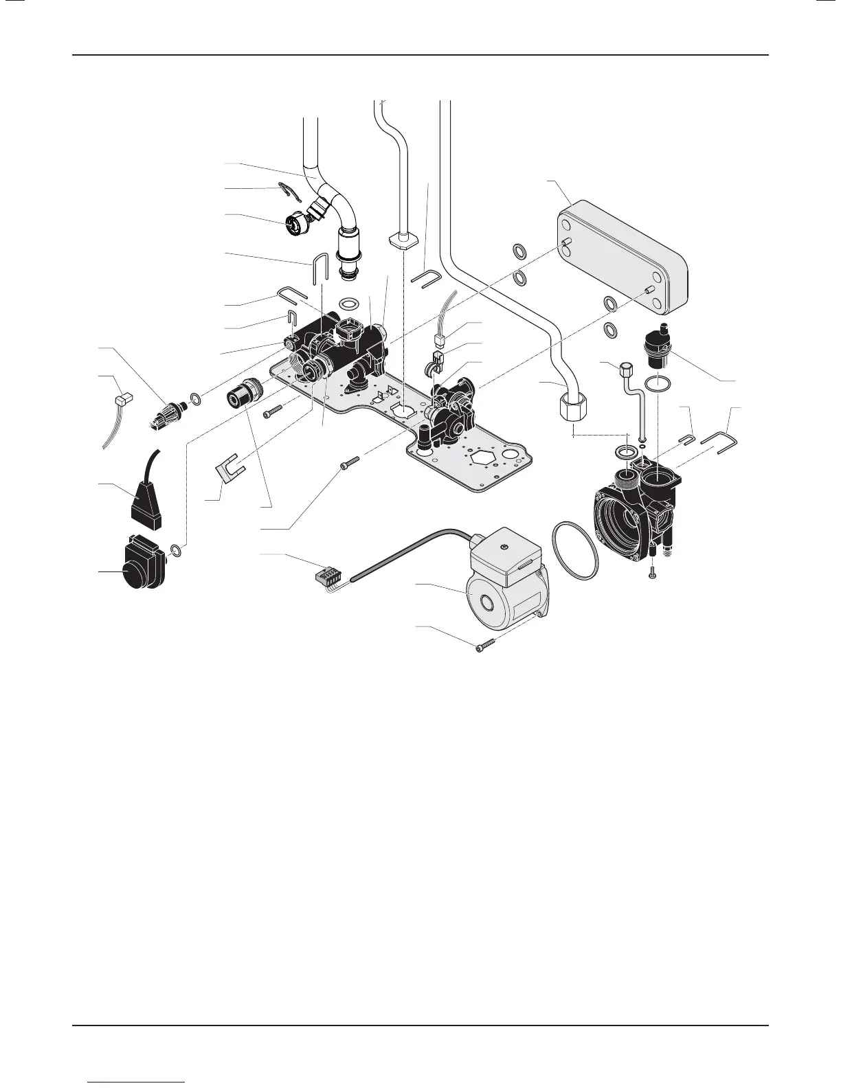
18.4 Hydraulic block
16
9
10
8
7
6
24
17
13
12
5
4
2
1
18
19
21
22
14
15
20
23
3
25
27
26
30
30
28
29
Key
1 Three-way valve
2 Three-way valve electrical plug
3 Three-way valve electrical plug retaining clip
4 Low water pressure sensor connector
5 Low water pressure sensor
6 Low water pressure sensor retaining clip
7 Heating fl ow pipe retaining clip
8 Manometer
9 Manometer retaining clip
10 Heating fl ow pipe
11 Gas pipe
12 Flow sensor electrical plug
13 Flow sensor
14 Heating return pipe
15 Expansion vessel pipe
16 Plate-to-plate heat exchanger
17 Automatic air vent
18 Expansion vessel pipe clip
19 Automatic air vent retaining clip
20 Pump head retaining screws
21 Pump housing
22 Pump head connector
23 Plate-to-plate heat exchanger retaining screws
24 Safety Discharge Valve
25 Bypass Valve
26 Bypass Valve retaining nut
27 Bypass Valve retaining nut
28 Impeller housing
29 Safety discharge valve plastic housing
30 Retaining clip
18.4.1 Pump (head only)
• Drain the boiler heating circuit as described in the appropriate
chapter "Draining".
• Disconnect the electrical plug (22) from the main board.
• Remove the four cap head screws (20).
• Carefully remove the pump head (21) together with cable.
Do not strain cable.
• Reconnect wiring to new pump head and fi t cover.
• Fit the new pump head by repeating the operations in reverse.
MAINTENANCE
- 41 -
 Loading...
