0020167175_01 - 02/13 - Glow-worm
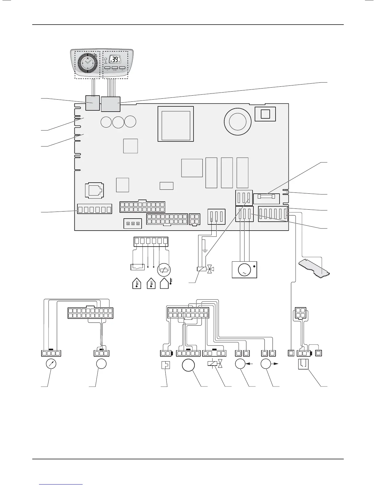
10.6 Wiring diagram
1
10
2
11
3
12
4
13
5
14
6
15
7
16
8
17
9
18
12
34
10987654321
1920 18 17 16 15 14 13 12 11
M
Green/Yellow
D
M
TT
NTC
Ebus
24 V
INTERFACECL
X2
X30
X90
X32
X40
X51
X31
X21
X13
230 VAC
LN
X1
X101
FUS
X14
X20
X17
X17
X15
123
10987654321
1920 18 17 16 15 14 13 12 11
3421
X2
12 34521 1 11 1...8921
1
10
2
11
3
12
4
13
5
14
6
15
7
16
8
17
9
18
X20
12
34
1
12
1
X21
Green/Yellow
Green/Yellow
18 17 16
1
2
3
4
9
6
5
8
7
1011121314
15
Key
1 Control accessories connector
2 Reserved for future use
3 Location for external accessories (condensate pump and options
board)
4 Internal timer
5 User interface
6 Fuse 2A
7 Connector for 230 V option
8 Main supply 230V
9 Pump
10 Combined spark and fl ame recognition electrode
11 Heating outlet temperature sensor
12 Heating return temperature sensor
13 Gas valve
14 Fan
15 Three way valve
16 Thermal fuse
17 Water fl ow sensor
18 Water pressure sensor
INSTALLATION
- 20 -
 Loading...
