20
User Manual V1.6-2022-01-05 02 Installation Instructions
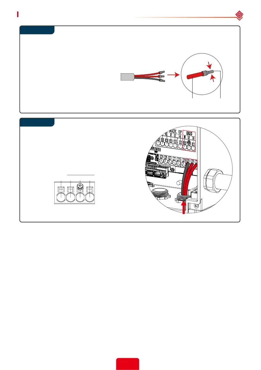
Use the correct wire ferrule from the accessory box. Crimp the ferrule onto
the conductor core tightly, as shown below.
Note:
Make sure the cable jacket is not
locked within the wire ferrule’s
crimped section. It is not necessary
to utilize a wire ferrule if using a
solid (non-stranded) conductor,
just remove the insulation.
Run the AC conductors (N, L1, L2) through a
conduit opening located either below or to
the right of the GRID terminals. Connect AC
conductors to GRID terminals.
2.4.5 Back-up Connection
Declaration for back-up function
The below statement lays out general policies governing the Hybrid inverters.
1. The back-up function needs the addition of a GoodWe auto-transformer for 120V back-up loads.
Otherwise, the o-grid function may not be used, and back-up loads may be damaged.
2. For A-ES series inverters, the installation typically consists of the inverter being connected to
both PV modules and batteries. In the case of systems not connected to batteries, it is strongly
advised not to use the back-up function. GoodWe shall not cover the standard warranty nor be
liable for any consequences arising from users not following this advice.
2. Under normal circumstances, the back-up switching time (aka, transfer time) is less than 10 ms
(comparable to some UPS devices). However, some external factors may cause the system to fail
on back-up mode. As such, we recommend the users to be aware of conditions and follow the
instructions as below:
• Do not connect loads if they depend on a stable energy supply for a reliable operation.
Step 1
TerminalCable
GRID
NL 1L 2
Step 2
 Loading...