24
User Manual V1.6-2022-01-05 02 Installation Instructions
100mm
200mm
300mm
300mm
100mm
(3.94 in.)
(3.94 in.)
(7.87 in.)
(11.81 in.)
(11.81 in.)
Expansion bolts
Wall-mounted bracket
Self-tapping Screws
Step 1
110mm
120mm
120mm
(4.33 in.)(4.72 in.)
(4.72 in.)
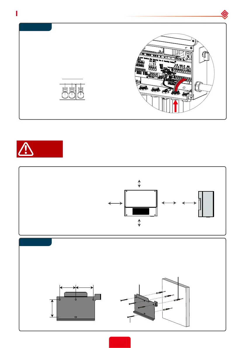
Run the Back-up conductors (N, L1, L2)
through a conduit opening located either
below the BACK UP terminals.
Connect the Back-up AC conductors to
BACK UP terminals.
2.4.6 Auto-transformer Connection (Optional)
The o-grid functions can be used only after the auto-transformer is installed.
The auto-transformer cannot be installed near ammable, explosive or
strong electro-magnetic equipment.
L’auto-transformateur ne peut pas être installé près de l’équipement
électromagnétique inammable, explosif ou solide.
Leave enough space around the auto-transformer according to the below
gure for natural heat dissipation.
Use the wall-mounted bracket as a template and drill holes in the wall, 10mm(0.39 in.) in
diameter and 80mm(3.15 in.) deep.
Fix the wall-mounted bracket on the wall using the expansion bolts in the accessories bag.
DANGER!
Upward ---------- 300mm (11.81 in.)
Downward ------ 300mm (11.81 in.)
Front -------------- 200mm (7.87 in.)
Both sides ------- 100mm (3.94 in.)
BACK UP
NL1L2
 Loading...