Repair
312066ZAD 39
Transducers
1. Turn main power OFF . Disconnect power
supply.
2. Relieve pressure, page 26.
3. Refer to electrical diagrams. Motor control board is
on right side inside cabinet.
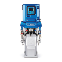
4. Disconnect transducer cables at board; see FIG.2,
page 38. Reverse A and B connections and check if
diagnostic code follows; see E21: No component A
transducer, page 15.
5. If transducer fails test, thread cable through top of
cabinet. Note path as cable must be replaced in
same way.
6. Install o-ring (820) on new transducer (806), FIG.3.
7. Install transducer in manifold. Mark end of cable
with tape (red=transducer A, blue=transducer B).
8. Route cable into cabinet and thread into bundle as
before.
9. Connect transducer cable at board; see FIG. 2, page
38.
Electric Fan
1. Turn main power OFF . Disconnect power
supply.
2. Relieve pressure, page 26.
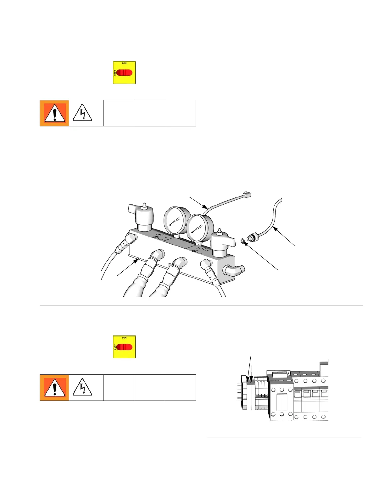
3. Check fuses (F) at left of breaker module, FIG.4.
Replace if blown. If good, continue with step 4.
4. Refer to electrical diagrams. Disconnect fan wires
from fuses (F).
5. Remove fan.
6. Install fan in reverse order.
FIG. 3. Transducers
TI10957a
820
806 (B Side)
801
806 (A Side)
FIG. 4. Fan Fuses
F
ti9884a-1

 Loading...