GREE DC Inverter Side Discharge VRF Ⅱ for North America
10
CONTROL
1 Units’ Control
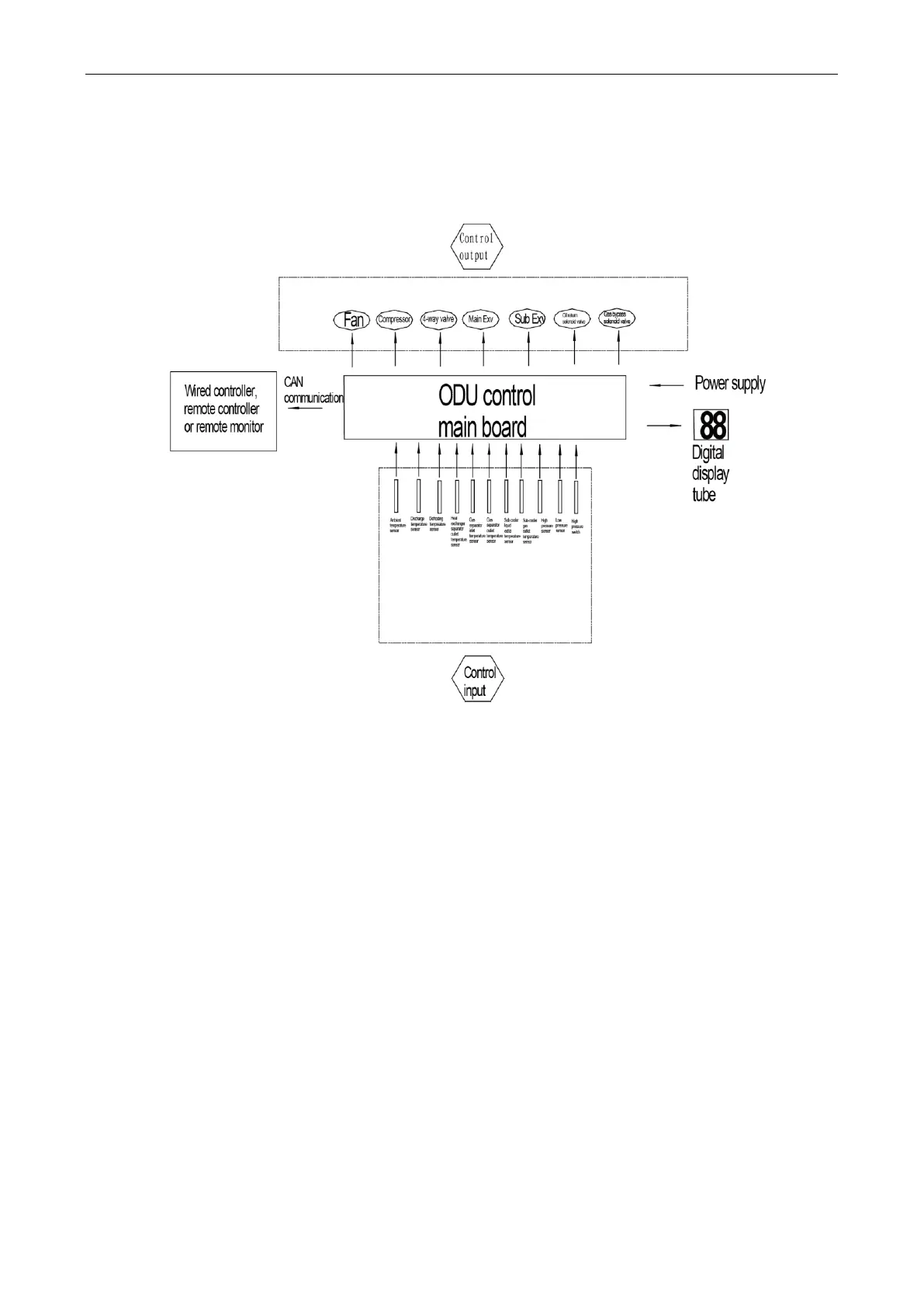
1.1 Schematic diagram of units’ control
Interpretation on the schematic diagram
(1) High pressure switch is used to identify system’s high and low pressure. When pressure is too
high, the switch will break off and send a signal to main board. Main board will pass this signal
to controller, where the error will be displayed, and stop unit from working.
(2) High/low pressure sensor is used to test unit’s high/low pressure and send real-time data to
controller, which will control each unit’s output according to the control logic.
(3) Temperature sensors are used to test the tube temperature of the unit and send data to the
controller, which will control each unit’s output according to the control logic.
 Loading...
