GREE DC Inverter Side Discharge VRF Ⅱ for North America
16
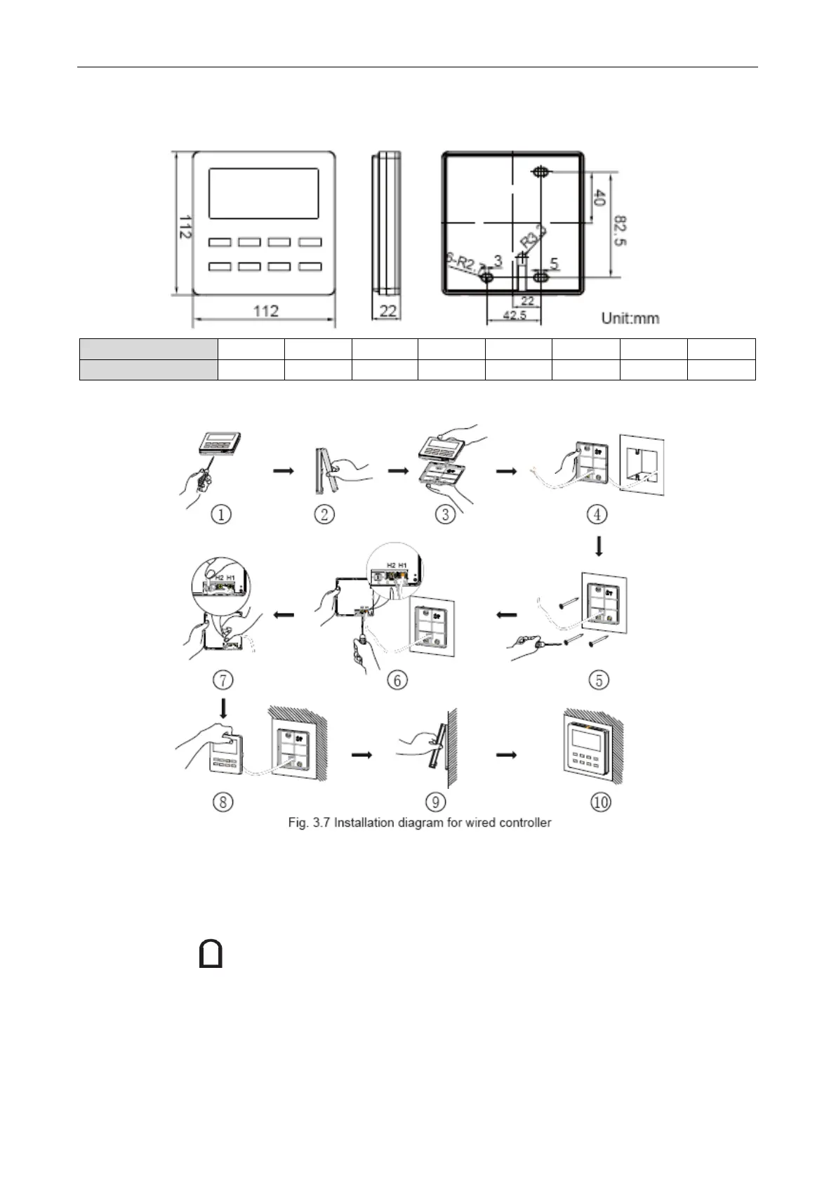
2.2 Installation and removal
2.2.1 Installation dimensions
2.2.2 Installation method
Above is a simple installation method of wired controller. Please pay attention to the following:
(1) Before installation, disconnect power of the indoor unit. Do not operate when power is
connected.
(2) Pull out the 2-core twisted pair cable from the installation hole on the wall and lead it through
the hole on the back plate of wired controller.
(3) Place the wired controller on wall and secure its back plate on wall with screw M4X25.
(4) Connect the 2-core twisted pair cable to terminal H1 and terminal H2. Tighten up the screws.
(5) Stick the cable in the slot that is left of the terminals and buckle the wired controller’s panel with
its back plate.
 Loading...
