GREE DC Inverter Side Discharge VRF Ⅱ for North America
78
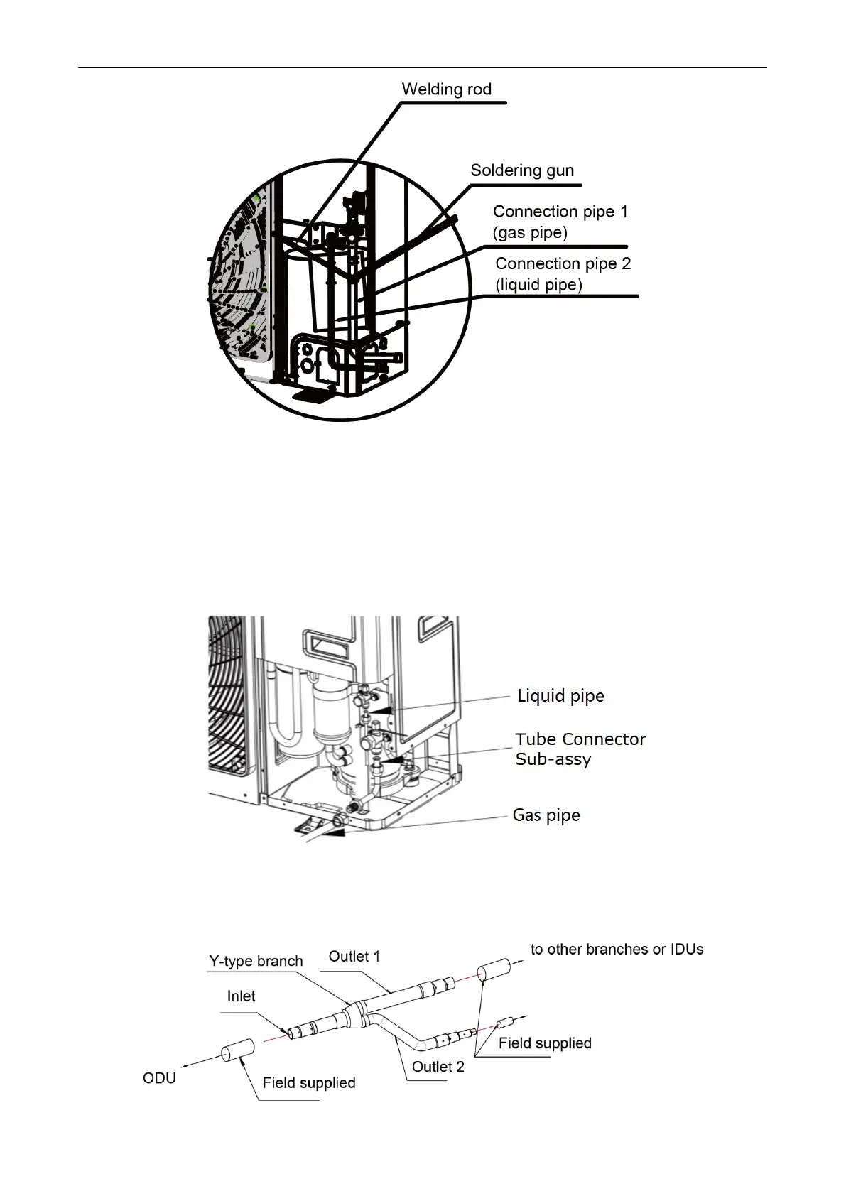
Fig. 17
(3) Twist the flared nut on the connection pipe of outdoor valves. Twisting method is the same as
for indoor pipe connection.
During engineering installation, the connection pipe inside the unit must be wrapped by insulation
sleeve.
Below is the piping diagram of GMV-24WL/C-T(U)
、
GMV-28WL/C-T(U). According to customer
requirement or space limit, outlet pipe can be installed from the front, right or rear side.
Fig. 18
6.1.4 Installation of Y-type Branch
(1) Y-type Branch
 Loading...
