GREE DC Inverter Side Discharge VRF Ⅱ for North America
48
then debugging will be finished step by step. For No.10 ODU Valves Check Before Startup, there are
“Back” and “Skip” buttons. If there is error in this step, you can back to step No.9 and click “OK” to restart
debugging on step No.10. If the error in step No.10 is U6 error (valve error alarm), you can click “Skip”.
In other cases, “Skip” button is null.
Step 11, 13 and 14 are reserved steps. And step 13, 14, 15 and 16 are steps in parallel (only one of
the four will be selected according to actual needs).
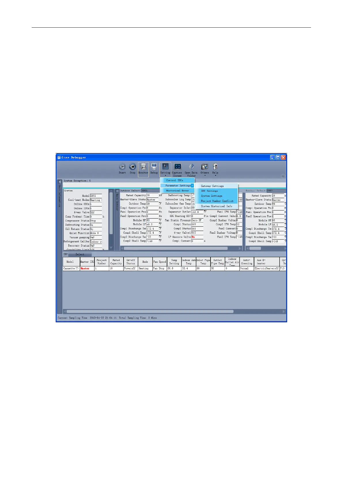
4.4.4 Control units
Click icon of “Setting” on menu bar and select parameter settings, which include “Gateway Settings”,
“IDU Settings”, “System Settings”, “Project Number Conflict (In case there is project number conflict in
indoor units, other functions will be shielded. Then this parameter needs to be set in order to eliminate
the conflict)” and “System Historical Info”. Click the corresponding set and adjust the parameters.
 Loading...
