EasyManuals Logo
Home>Gree>Inverter>GMV-24WL/C-T

Gree GMV-24WL/C-T Service Manual

Gree GMV-24WL/C-T
150 pages
To Next Page IconTo Next Page
To Previous Page IconTo Previous Page
Page #88 background imageLoading...
Page #88 background image
GREE DC Inverter Side Discharge VRF for North America
85
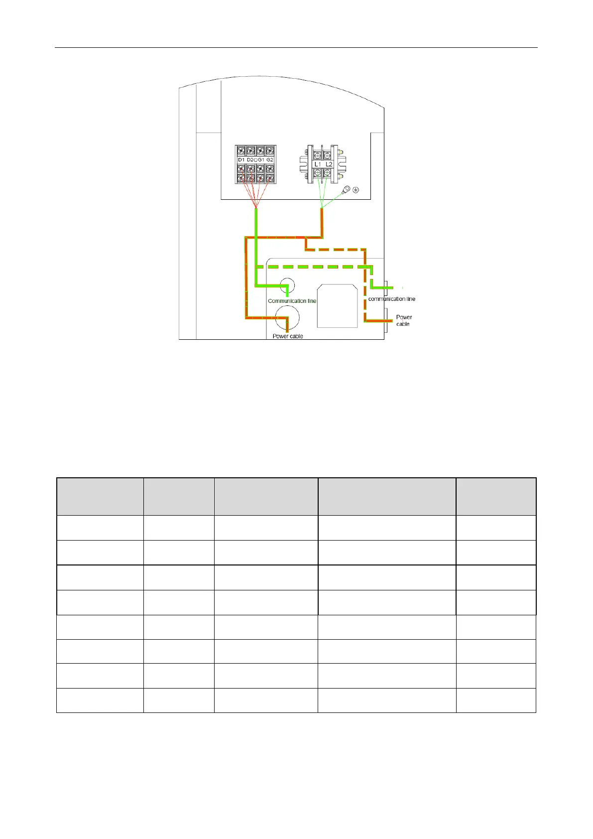
(2) The wiring diagram for power cord of outdoor unit and communication wire.
There are two wiring diagrams for communication wires of indoor/outdoor units and remote monitor:
1) Real line method;
2) Broken line method. Please select it based on the actual installation situation.
There are two wiring diagrams for power cord:
1) Real line method;
2) Broken line method. Please select it based on the actual installation situation.
7.2 Power Cable Wire Gauge and Circuit Breaker Selection
Model
Power supply
Max Fuse Size/Fusible
Max.
(A)
Max Ckt, Bkr Size/Disjoncteur
Max. (A)
Min. Circuit
Ampacity
(A)
GMV-24WL/C-T(U)
208/230V~
60Hz
25
25
21
GMV-28WL/C-T(U)
208/230V~
60Hz
30
30
21
GMV-36WL/A-T(U)
208/230V~
60Hz
35
35
31
GMV-48WL/A-T(U)
208/230V~
60Hz
45
45
34
GMV-60WL/A-T(U)
208/230V~
60Hz
60
60
39.8
GMV-36WL/C-T(U)
208/230V~
60Hz
35
35
28.5
GMV-48WL/C-T(U)
208/230V~
60Hz
40
40
33
GMV-60WL/C-T(U)
208/230V~
60Hz
40
40
34.5

Table of Contents

Other manuals for Gree GMV-24WL/C-T

Questions and Answers:

Question and Answer IconNeed help?

Do you have a question about the Gree GMV-24WL/C-T and is the answer not in the manual?

Gree GMV-24WL/C-T Specifications

General IconGeneral
BrandGree
ModelGMV-24WL/C-T
CategoryInverter
LanguageEnglish

Related product manuals