Gree VRF Protocol Gateway
10
3 Product Installation
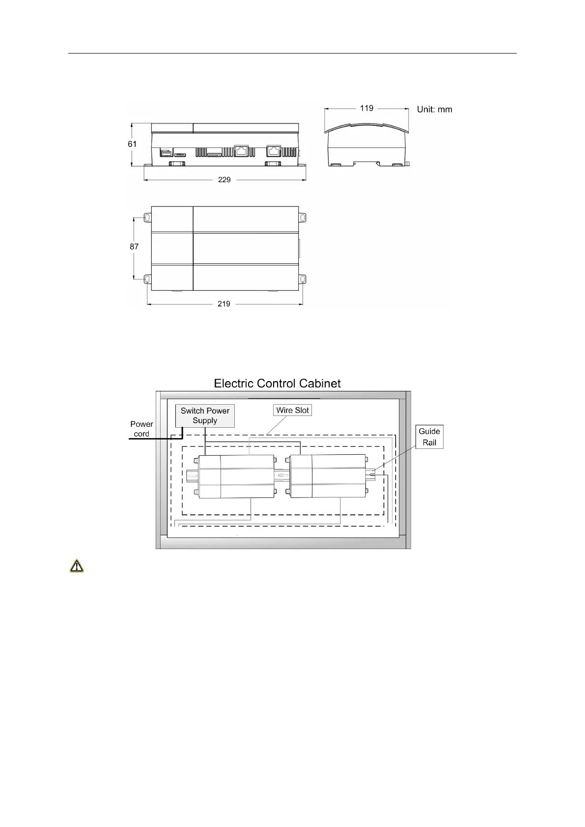
3.1 Product Size
3.2 Spatial Size for Electric Control Cabinet Installation
Gateway shall be installed in electric control cabinet; the front of gateway shall be hung
upward and fixed with 4 screws. See the following fig (for reference).
WARNING!
Power cord and communication line of Gateway must conduct routing separately (the distance
shall be over 15cm); otherwise, it might lead to Gateway communication malfunction!
The thin real line shown in the figure is communication wire and weak current wire, the thick real line is strong
current wire. Above lines are only for reference.
4 Gateway and BMS adopt Modbus RTU communication
connecting method
Gateway communication system include:
(1) The communication between the gateway and BMS;
(2) The communication between the gateway and air conditioner.
 Loading...