Gree VRF Protocol Gateway
12
NOTICE!
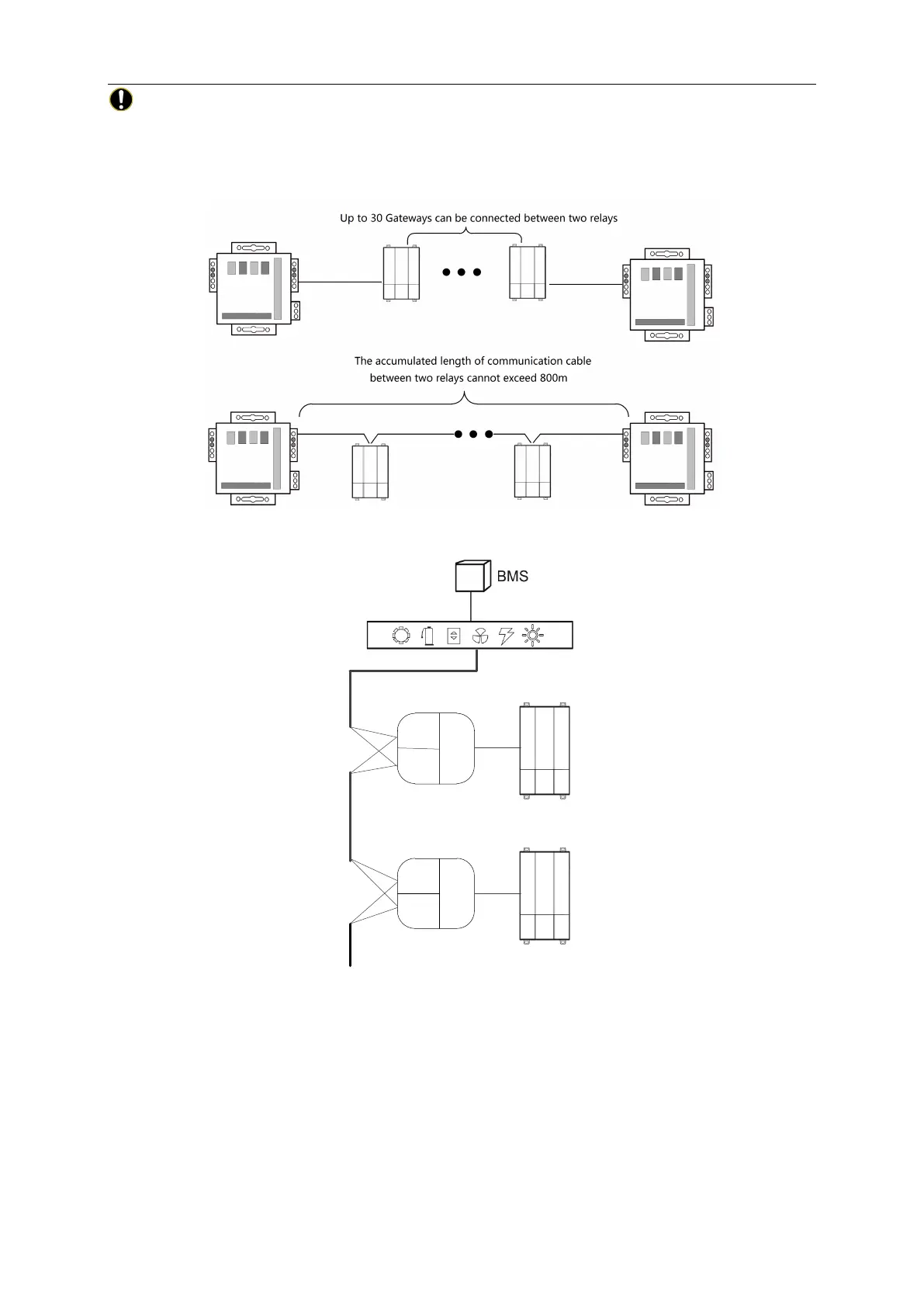
In the Modbus, when the quantity of connected gateway exceeds 30 or the
communication distance exceeds 800m, one more PV isolation relay should be added, and
connect the R+ and R- terminals of PV isolation relay to the RS485-1 communication interfaces
R+ and R- of the adjacent gateway.
4.3 Setting of communication connection
RS485-1
R+ R-
(A1) (B1)
RS485-1
R+ R-
(A1) (B1)
①
②
③
Gateway
Gateway
Step 1: Ensure the first gateway that should connect to BMS terminal, connect the RS485-1
communication interfaces R+ and R- of the gateway to the BMS terminal with communication
cable; as shown in Step
①
in the figure.
Step 2: Connect the RS485-1 communication interfaces R+ and R- of the gateway to the
RS485-1 communication interfaces R+ and R- of the second gateway with communication cable;
as shown in Step
②
in the figure.
Step 3: Connect other gateways in turn; as shown in Step
③
in the figure.
 Loading...