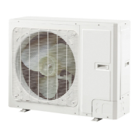
Gree VRF Protocol Gateway
7
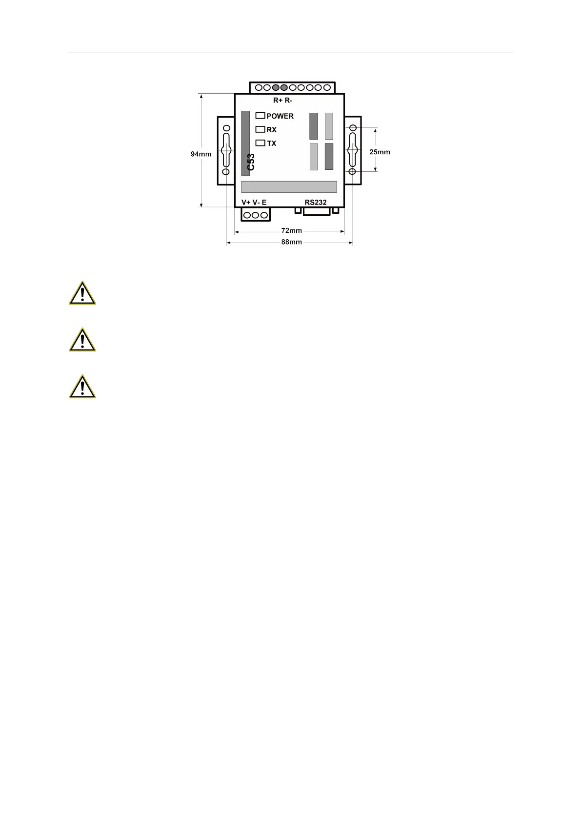
2.3.4 Dimension
2.3.5 Notices for installation
Warning!
It must be fixed indoors to avoid collision, exposure to the sun or rain. It is
recommended to place it in the monitoring room with the computer.
Warning!
The original equipment of the manufacturer must be used, and it is not allowed to
purchase alternative products of other models or brands.
Warning!
An independent power supply is required, and sufficient 220V AC outlet must be
installed to supply power.
2.4 Introduction to optical isolation relay
2.4.1 Introduction to functions
Function of optical isolation relay:
(3) When the distance of the entire communication network node exceeds 800 meters,
the optical isolation relay is to ensure the signal integrity and prevent the signal from
attenuating in the case of long-distance communication.
(4) At present, the general optical isolation relay can support the integrity of the
communication signal of 32 nodes. When the number of communication nodes in the
network exceeds 32, the communication signal will be incomplete. In order to ensure
the reliable transmission of signals, we require that when the number of nodes in the
network exceeds 30, a relay must be used to transmit the signal to ensure the
integrity of the communication signal.
 Loading...