Gree VRF Protocol Gateway
5
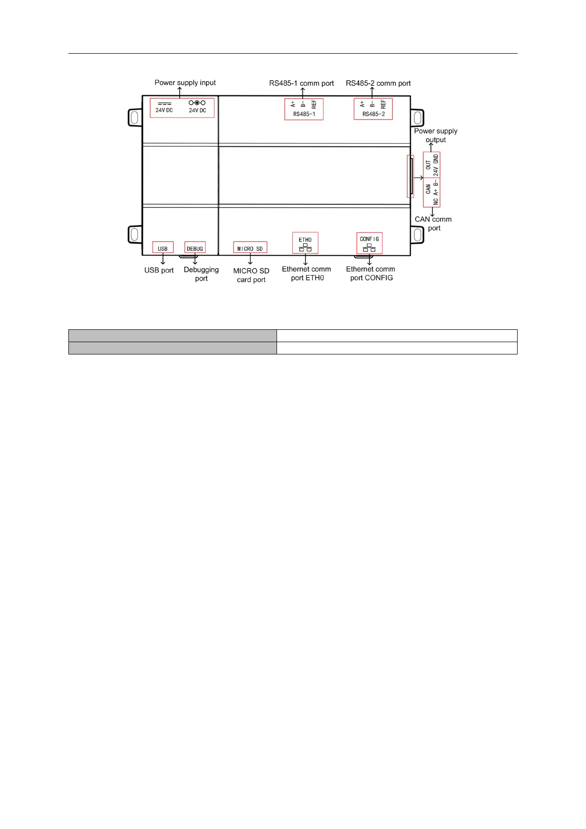
2.2.2 Phicture of Gateway and Interfaces
2.2.3 Components
Gree VRF protocol gateway kit ME30-24/D1(BM) includes the following components:
2.2.4 Interface
(1) Power
The input power supply is 24V DC, there are two power supply input interfaces, only one is
needed during operation; the power supply output is not applicable in this device, please do not
connect to electric appliance, otherwise it may cause malfunction of gateway.
(2) Communication Interface
CAN comm port:
connect it to the AC unit through the 2-core communication line to realize
the communication between Gateway and the AC which adopts CAN protocol.
RS485-1 comm port:
connect to the BMS terminal through a two-core communication line to
realize the communication connection between the gateway and the BMS terminal or the
connection between adjacent gateways.
RS485-2 comm port:
this device will not use this communication interface temporarily.
USB and SD card port:
this device will not use this interface temporarily.
Ethernet comm port ETH0:
realize communication through network cable and BMS.
Ethernet comm port CONFIG:
this device will not use this interface temporarily.
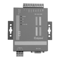
2.3 Introduction to optical isolation convertor
2.3.1 Introduction to functions
The role of the optical isolation converter is to convert the RS232 signal of the computer serial
port and the signal of the RS485 bus. Only needed when the user’s BMS is RS232
communication.
 Loading...