Float switch
Configuration
1 2 3 4
2 - - - High level
1 - High level Dry running Dry running
Related information
8.1.1 Primary settings
8.1.4 Float switch functions
8.1.3 Pump delays
8.2.14 Start level variation
8.1.5 Out of operation
This display allows the user to take a pump temporarily out of
operation for service or due to operational disturbances.
When a pump is taken out of operation, it is removed from the list of
pumps that can be started. The system continues to operate with
the remaining pump(s).
Example 1
Select the pump to be taken out of operation.
• Pump 1 (out of operation)
• Pump 2 (in operation).
Example 2
Pump 1 is taken out of operation, and alternating operation is
enabled. The system continues to operate with only one pump. This
pump is now controlled by the start/stop levels for pump 2. This
applies no matter which of the pumps is taken out of operation. If
alternating operation is disabled, the remaining operating pump is
controlled by its own start/stop levels.
The user can take a faulty or inefficient pump out of operation.
Taking a pump out of operation removes the need to send its
alarms/warnings to the SCADA system.
The pumps always have a designated number, whether
alternating operation is enabled or disabled.
Path: Settings > Basic functions > Out of operation
4-1-5_OUT_OF_OPERATION_044
Out of operation
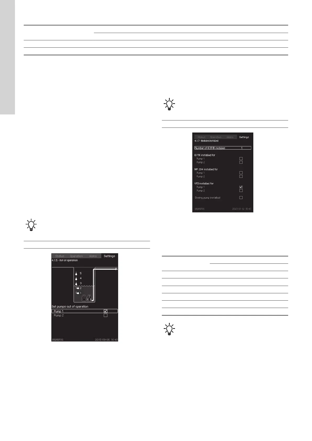
8.1.6 Modules installed
This display allows the user to configure the Dedicated Controls
system.
The number of IO 351B modules installed in the system must be
entered.
For each pump, tick the box if the mentioned module, motor
protector or frequency converter has been installed.
• IO 351B (maximum three modules).
• IO 113 (one module for each pump, maximum 6).
• MP 204 (one module for each pump, maximum 6). NOT to be
used together with a CUE or VFD.
• CUE or VFD.
When a module is selected, the data from the module can be seen
in the "Pump x" status display. See section about specific pump.
The status values depend on the actual configuration of the system.
These settings enable the modules selected
and the functions related to each module.
Path: Settings > Basic functions > Modules installed
TM078589
Modules installed
IO 113 installed for
Tick "Pump 1" or "Pump 2" to indicate that an IO 113 module has
been installed for that pump.
GENIbus number (address)
Pump number
Module
IO 113 * MP 204 ** CUE
1 9 (40) 1 1
2 10 (41) 2 2
3 11 (42) 3 3
4 12 (43) 4 4
5 13 (44) 5 5
6 14 (45) 6 6
The GENIbus number (address) can be set using the DIP
switches on the IO 113 module.
*The DIP switches on the IO 113 module must be set to bus
configuration if the IO 113 module is to be configured by use of a
PC Tool. See the installation and operating instructions for IO 113.
**MP 204 cannot be used together with CUE.
The Grundfos SM 113 module is partly supported, meaning
that only alarms are supported. Status values cannot be used or
seen on CU 362. When using SM 113 together with IO 113, IO 113
must have communication built in to support SM 113.
Related information
5.3 Specific pump
8.2
Advanced functions
The display shows the options in this menu.
30
English (GB)

 Loading...