16
Installation
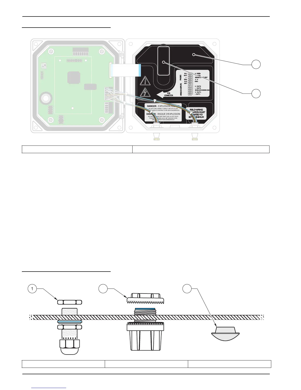
Figure 10 Removing Voltage Barrier
3.3.1 Installation in Conduit
In hard-wired electrical applications, the power and safety ground service drops for the
instrument must be 18 to 12 AWG. See Figure 11 on page 16 for strain relief and conduit
opening sealing plug information. See section 3.3.3 on page 17 for wiring information.
3.3.2 Installation Using a Power Cord
DANGER
Use of a power cord is not acceptable in Class 1, Division 2 Hazardous Location
Installation (see Hazardous Location Installation Control Drawing on page 10).
A sealing-type strain relief to maintain the NEMA 4X/IP66 environmental rating and a
power cord less than 3 meters (10 feet) in length with three 18-gauge conductors
(including a safety ground wire) can be used, see Replacement Parts and Accessories on
page 43. See Figure 11 on page 16 for strain relief and conduit opening sealing plug
assembly. See section 3.3.3 on page 17 for wiring information.
Figure 11 Using the Optional Strain Relief and Conduit Plug
1. High voltage barrier 2. Unsnap the barrier latch then pull out to remove the barrier.
NCNCNC
COMCOMCOM
NO
F1
F2
NONO
RELAY CRELAY B
DANGER - EXPLOSION HAZARD
DANGER - RISQUE D'EXPLOSION
DO NOT DISCONNECT WHILE CIRCUIT IS LIVE
UNLESS AREA IS KNOWN TO BE NON-HAZARDOUS.
NE PAS DEBRANCHER TANT QUE LE EST SOUS
TENSION, A MONIS QU'IL NE S'AGISSE D'UN
EMPLACEMENT NON-DANGEROUX
J1
J2
J4
NETWORK
INTERFACE
CARD
J3
J5
J6
U5
U9
S1
NCNCNC
COMCOMCOM
NO
F1
F2
NONO
RELAY CRELAY BRELAY BRELAY ARELAY A
1
1
+ DATA+ DATA
+ OUT 2+ OUT 2
– DATA
– OUT 2
SERVICE REQUEST
SHIELD/CHASSIS GND
+ V+ V
+ OUT 1+ OUT 1
GND
– OUT 1
2
2
3
3
4
4
5
5
6
PROBES
ANALOG OUTPUTSANALOG OUTPUTS
PCB
CONNECTOR
PCB
CONNECTOR
FIELD WIRING
INSULATION MUST
BE RATED TO
80° C MINIMUM
FIELD WIRING
INSULATION MUST
BE RATED TO
80° C MINIMUM
DANGER - EXPLOSION HAZARD
DANGER - RISQUE D'EXPLOSION
DO NOT DISCONNECT WHILE CIRCUIT IS LIVE
UNLESS AREA IS KNOWN TO BE NON-HAZARDOUS.
NE PAS DEBRANCHER TANT QUE LE EST SOUS
TENSION, A MONIS QU'IL NE S'AGISSE D'UN
EMPLACEMENT NON-DANGEROUX
J1
J2
J4
NETWORK
INTERFACE
CARD
J3
J5
J6
U5
U9
S1
 Loading...