21
Installation
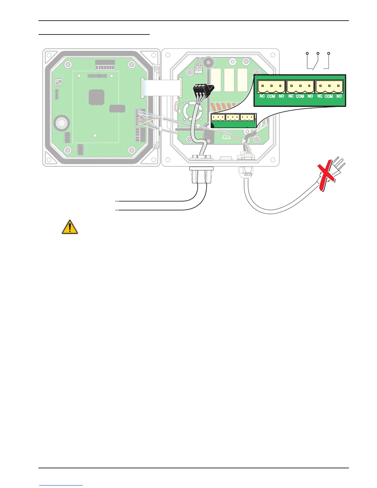
Figure 16 Alarm and Relay Connections
3.4.2 Connecting the Analog Outputs
DANGER
Explosion hazard. Do not connect or disconnect electrical components or circuits
to the equipment unless power has been switched off or the area is known to be
non-hazardous.
DANGER
For Class 1, Division 2 Hazardous Location installations, refer to the Control
Drawing (Figure 2 on page 10) for permanent connection requirements for the
analog output.
Two isolated analog outputs (1 and 2) are provided, see Figure 17. Each output can be set
to 0–20 or 4–20 mA, and can be assigned to represent the measured parameter or
secondary measurement such as temperature. Make connections with twisted-pair
shielded wire and connect the shield at the controlled component end or at the control
loop end. Do not connect the shield at both ends of the cable. Use of non-shielded
cable may result in radio frequency emission or susceptibility levels higher than allowed.
Maximum loop resistance is 500 ohm. Refer to the sensor manual for output software
setup.
Make wiring connections at the analyzer end as shown in Table 4 and Figure 17.
NCNCNC
COMCOMCOM
NO
F1
F2
NONO
RELAY CRELAY BRELAY A
J1
J2
J4
S1
NETWORK
INTERFACE
CARD
J3
J5
J6
U5
U9
J5J5
 Loading...