3-90-00674R20_08/12
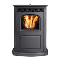
Fig. 32
•The green wire with a female terminal is the stove body
ground. See Fig. 32
• On the combustion air inlet box there is a male terminal
ground.
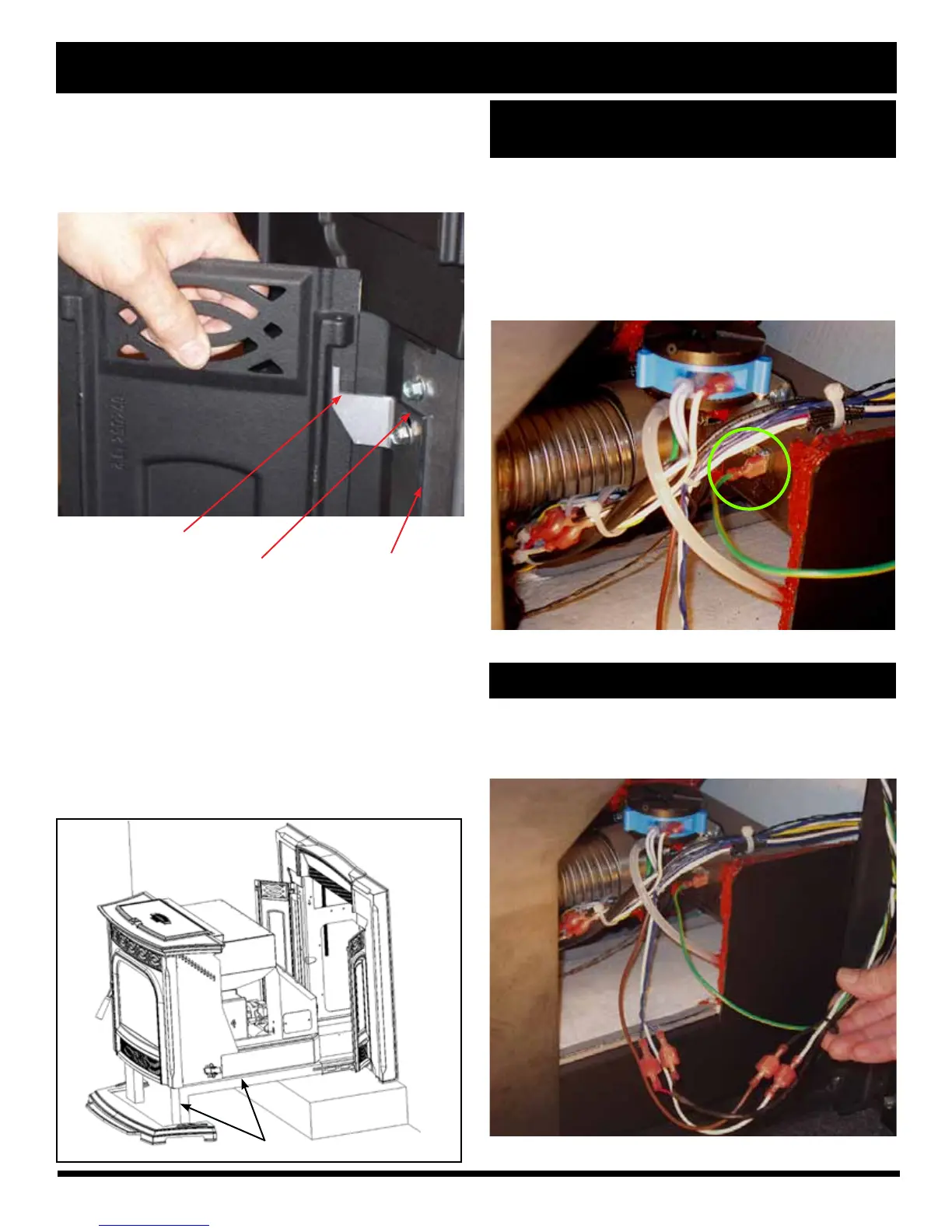
Fig. 33
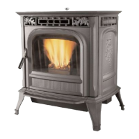
Install the cast side panels by sliding them down
over the lasered hinge pin. Note: Check for rotational
swing, but nish with them in the open position. The
cast side panels may need adjustment after the stove
body is latched into place and the front door is closed.
The white from the mounting frame connects to the
white of the insert body. The black from the mounting
frame connects to the brown of the insert body.
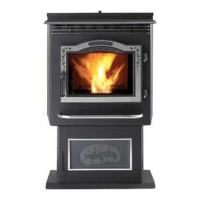
Place the stove body on the mounting shell
gasketed rails and insert the body into the opening far
enough that it can't tip out. Note: A service rail kit (Part
#1-00-08007), or a pair of 2 x 4's supported in front of
the hearth will make this job easier. See Fig. 31.
Complete the following electrical connections
(CAUTION: Disconnect the power cord.) There are 5
connections that must be completed. See Fig. 33 & 34.
Fig. 30
Lasered hinge pin
pivoting point
Up and down
clearance adjustment
slots.
Cast side
panel hinge
Fig.31
2 x 4
 Loading...