3-90-00674R20_08/12
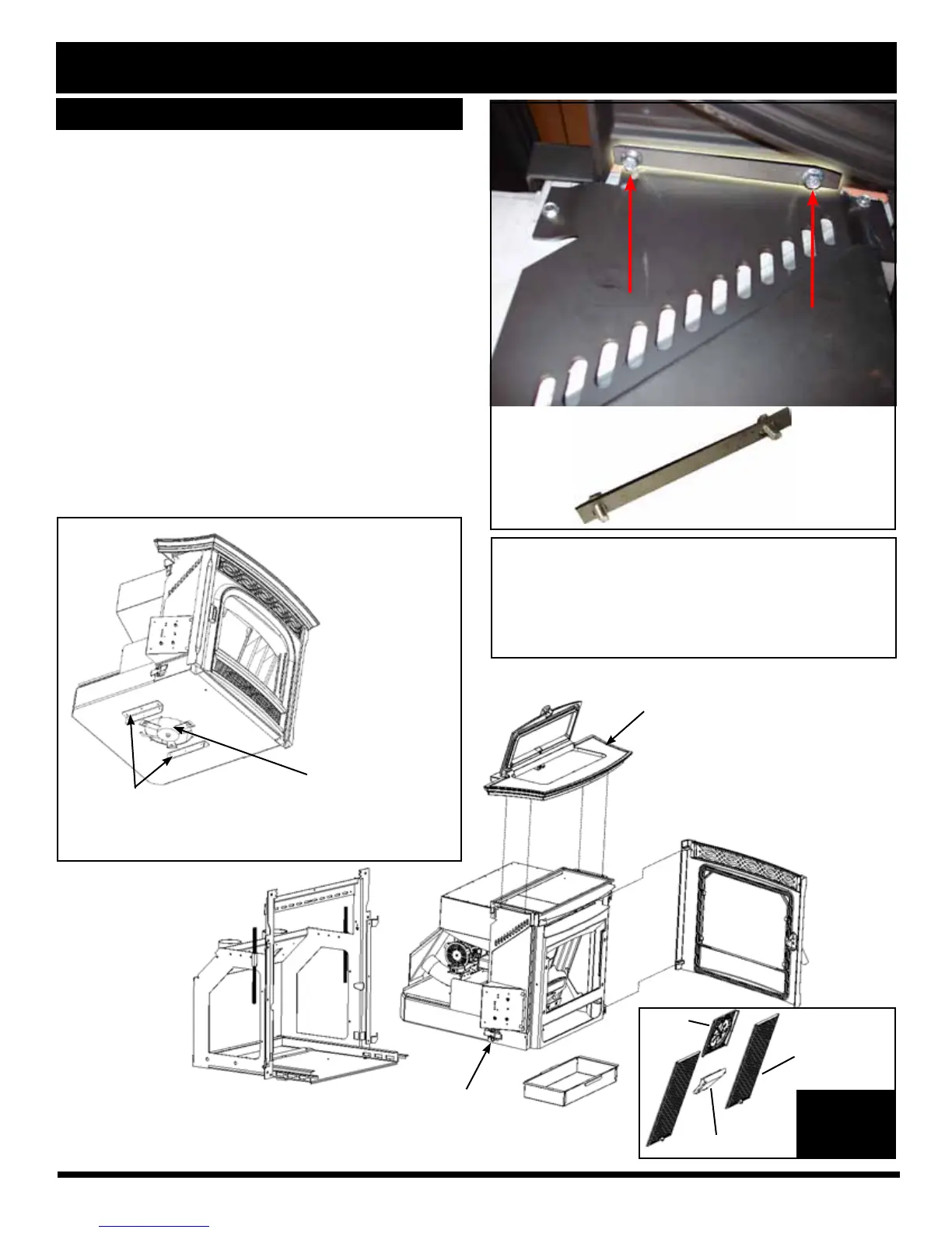
When removing the top and lid assembly,
rst remove the hopper lid position switch from its
mounting bracket. Loosen the switch retainer nut,
and allow the switch to drop out of the bracket.
Top and Lid Assembly
Center
Medallion
Flame Guide
Heat
Exchanger
Cover
Ash Pan
(2) Spring Latches
(One on each side)
Fig. 11
1. Remove the top/lid assembly and side panels.
•
• Note: The hopper lid must be in the "OPEN" position
before the top/lid assembly can be lifted off or reinstalled
on the stove body.
• There are (4) 1/4-20 x 1/2" ange head bolts securing
the top/lid assembly to the stove body. They can be
removed from the underside with a 3/8" socket.
On each side of the stove body, underneath the cast
top, are (2) 1/4" ange head bolts. See Fig. 12.
These bolts pull the cast top and lid assembly down
onto the hopper gasket to seal the hopper.
They also allow for a small amount of front to back
adjustment for alignment of the top into the wing
pockets.
Mounting Shell
Protector Angles: These angles are designed
to protect the blower motor from damage when
placed on a at surface. Be careful where and
how the stove body is handled.
B e c a r e f ul no t
to da ma ge th e
distribution blower
located under the
insert. There are
guards on both
sides of the motor
to allow the insert
to rest on a flat
surface, however,
extra care should
be taken.
Distribution Blower
Fig. 10
Fig. 12
 Loading...