21
Pellets or Corn/Pellet Mixture Only
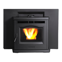
P35i Fireplace Insert
Save These Instructions 3-90-775R15_04/13
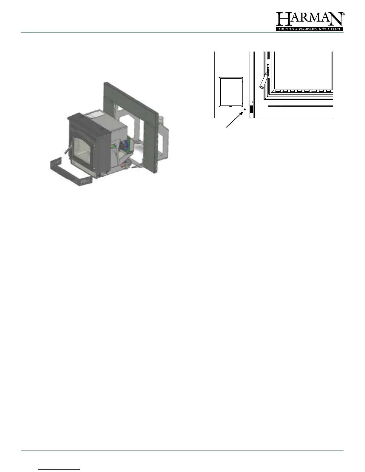
Room sensor placed here gives an accurate measure of return air.
Push the pre-cut hole inward, and feed the sensor from the back
side. Allow the bulb of the sensor to extend approximately 1½
inches into the room. Use a wire tie on the push-in tab to secure
the sensor wire.
G. Control Board Installation
Thecontrolboardispackagedinastaticresistantbag.
Use care when handling, hold the circuit board only
bytheedges. Ina large replaceopening, you may
have plenty of space for the circuit board to remain
attached.Forasmallerreplaceopening,you'lllikely
need to remove the wiring from the circuit board to
routeitthroughthesideofthemountingframeandout
throughthecontrolopening.Followthesesteps;
• Disconnectthe11pinharnessplug.
• DisconnecttheredtwistedESPwire.
• FeedtheharnesswiresandtheESPwirethrough
theopeninginthemountingframeandoutthrough
thecontrolopeninginthesurroundpanel.
• Holding thecontrol board outside the openingin
thesurroundpanel,re-attachtheharnessplugand
theESPwire.
• AfterdeterminingthelocationoftheRoomSensor
(SeenextSection),Attachittothetwomalespade
terminalsnearthetopofthecircuitboard.
NOTE:Theseconnectionsarenotpolarityspecic.
• From the power cord, attach the green ground
wireto the groundingpost locatedon the feeder
airintakesnout.
• Theblackwirefromthepowercordgetsattached
totheshortbrownwirefromthecontrolharness
• Thewhitewirefromthepowercordwillattachto
theshortwhitewireonthecontrolharness.
• Install the control panel into the surround; Right
siderst,thentiltintheleftside.
• Secure using the four black machine screws
includedwiththesurround.
H. Room Sensor Installation
Although not required, it is recommended that the
roomsensorbeconnectedineveryinstallation.Using
aminimumsize18gaugewire,youmayspliceinan
additional length, to extend the room sensor. The
followingaretypicallocationsfortheroomsensor;
• Onaninteriorwallnexttoorinplaceofatypical
wallthermostat.
• Onthe leg ofa coffeetable orend tablein your
favoritesittinglocation.
• Stickingoutthroughthepunchedholeatthelower
rightcornerofthecontrolpanel.
Note: When installing the room sensor externally,
limit the distance from the stove to 25 feet or less.
Once the location has been decided, run the wiring
to the control panel. You'll need to remove the two
terminalsfromtheendofthesensorcableandreplace
themwiththetwosmallerterminalsfromthehardware
bag.Plug theterminalsinto thecircuit board.These
connectionsarenotpolarityspecic.
Note: If the room sensor is located too close to the
appliance, or in a direct path of the distribution air,
You may need to elevate the temperature setting
to maintain a comfortable temperature level
throughout the heated space.
See Draft Test Procedure on Page 26.
F. Installing the Body into the
Mounting Frame
Therollersonthesidesoftheinsertbodywillrideon
therailsofthemountingframe.Oncethebodyisall
thewayin,hookandclosethetopspringlatcheson
eachsidetosecure.
 Loading...