Harman® • P-Series Installation Manual_R3 • 2014 -___ • 09/1411 3-90-436168i
4
Termination Location and Vent Information
A. Vent Termination Minimum Clearances
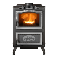
Figure 4.1
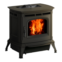
Figure 4.2
#1 Preferred method (Figure 4.1)
Thismethodprovidesexcellentventingfornormaloperation
andallowsthestovetobeinstalledclosesttothewall.Two
inches from the wall is safe; however, four inches allows
betteraccesstoremovetherearpanel.Theverticalportionof
theventshouldbethreetovefeethigh.Thisverticalsection
willhelpprovidenaturaldraftintheeventofapowerfailure.
Sealpipejointswithsiliconeoraluminumtapeinadditionto
thesealingsystemusedbythemanufacturer.
Note: Do not place joints within wall pass-through.
#2 Preferred method
(Figure 4.2)
This method also provides excellent venting for normal
operationbutrequiresthestovetobeinstalledfartherfrom
thewall.Theverticalportionoftheventshouldbethreeto
vefeethighandatleast1”fromacombustiblewall.This
vertical section will provide natural draft in the event of a
powerfailure.
Sealpipejointswithsiliconeoraluminumtapeinadditionto
thesealingsystemusedbythemanufacturer.
If the stove is installed below grade be sure the vent
termination is at least 12" above grade (with outside air
only).Theoutletmustalsobe1footfromthehouse/building.
Note: Do not place joints within wall pass-through.
CAUTION
Keep combustible materials (such as grass, leaves,
etc.) at least 3 feet away from the ue outlet on the
outside of the building.
3 Ft.
to
Combustibles
3 Ft.
to Combustibles
3 Ft.
to
Combustibles
3 Ft.
to Combustibles
 Loading...