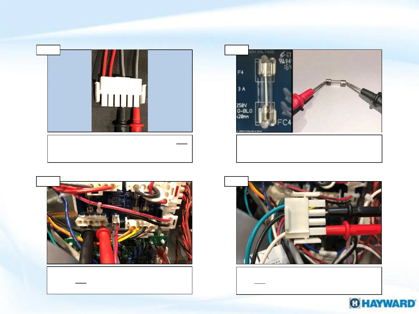
Verify ICB output
Disconnect the P6 connector and test voltage for
110-125VAC between pins 3-5. IF no/low voltage,
go to step 5D. IF correct, go to 5D.
Disconnect the E10 connector from ICB. Verify 110-
125VAC between 1-3 (white & black). IF present,
replace ICB. IF NOT, replace wire harness (pg. 25).
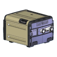
Verify ICB input
Step 5C
38
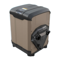
Step 5D
5. Service LED ON: ‘BD’ Code
Disconnect P4 from fuse board. Verify 110-125VAC
between 4-6 (grey wires). IF OK, replace fuse
board. IF NOT, replace transformer (pg. 25).
Verify transformer output
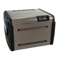
Step 5A
With power off, verify the FC4 fuse has continuity.
IF fuse is good, go to 5B. IF fuse is blown, go to
Page 33.
Test the FC4 fuse (continuity)
Step 5B
 Loading...