15
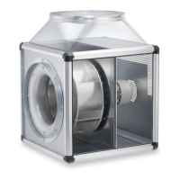
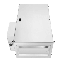
Fresh Air Boxes
Installation and Operating Instructions
Connection of protective conductor (PE) via PE terminal (fig. 5),
Connection of power supply via main switch (fig. 4):
1 ~ 230V L1/N/
3 ~ 400V L1/L2/L3/N/
(L1= control phase)
Never run cable over sharp edges!
Check direction of rotation of fan!
6.3 Connection of warm water heater battery (for types ..WW)
The installation must be carried out by a professional company, which will also perform a pressure test on the
connection.
- Max. permissible water temperature +90 °C
(there must be no steam in the heater battery).
- Max. permissible water pressure 16 Bar.
- Water connection: external thread G1.
- The units are equipped with a frost protection sensor. The frost protection is already connected and set.
Requirement for perfect operation:
- The connected heating system must always provide warm water.
The heat recovery must be ensured during the night reduction of the heating system.
- The heating system may not be switched off (holiday period, weekend)
- The ventilation system must be equipped with an external electrical damper so that no cold outside air can enter the
switched off ventilation system.
- The ALB must always be frost-protected.
- Heat supply through night reduction of heating system.
There is danger of frost if the mains power supply is switched off!
6.4 Connection of external components
6.4.1 Connection of control unit (Fig. 7)
The control panel unit must be connected to start the ventilation unit.
- Remove the securing screw from the lower part of the control unit.
- Open the casing of the control unit.
- Cut out opening for the cable.
- Connect control line to the RJ socket in the control unit.
- Fix control unit to a wall.
- Close casing and secure with screw.
- Connect the other end of the control line to any free RJ socket
in the circuit board of the ALB.
- Maximum cable length 50 m.
- The control line must be an appropriate distance from the power cables.
- The connector must snap when connecting.
- When fastening the control line to the wall or the like. the isolation must not be damaged.
- If the control line is not connected directly after installation, its ends must be isolated.
- The control line connector must not come into contact with water or other liquids.
ATTENTION
Fig.4 Fig .5 Fig .6
Power supply
L
1, L2, L3
ATTENTION
ATTENTION
ATTENTION
Fig.7
ATTENTION
UK
RJ socket
M
ains switch
present in
main unit
Main unit
EH type
Supply line
Electric heater
External mains switch
must be present
Supply line
Unit
An all-pole mains switch / isolator switch with
at least 3mm contact opening is mandatory
(according to DIN EN 60335-1)
 Loading...