DS-2TD2xxx-xx/xx Thermal and Optical Bi-Spectrum Network Bullet Camera Quick Start Guide
QSG DS-2TD2xxx-xx/xx 071720NA 12
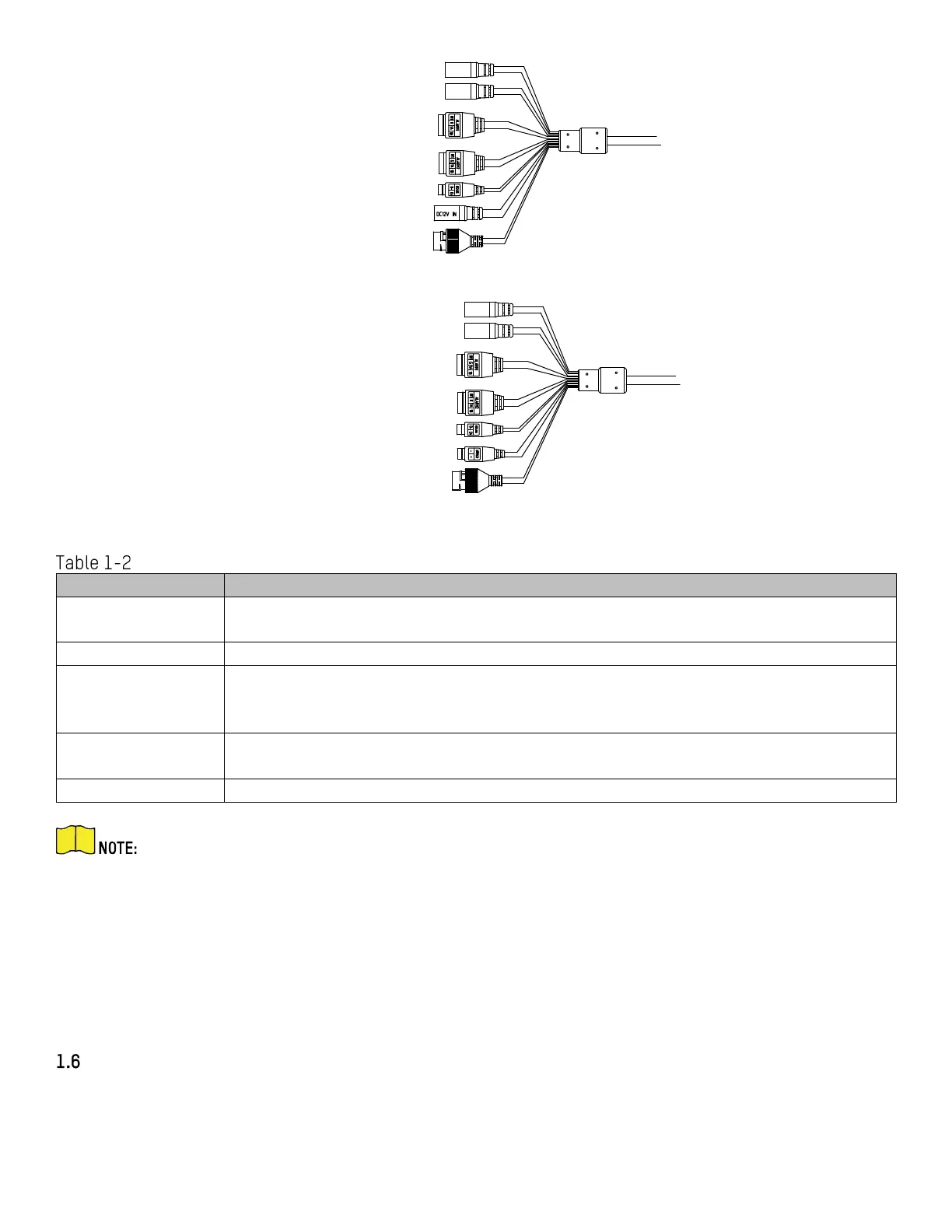
Alarm Interface 1
Audio Output Interface
Alarm Interface 2
RS-485 Interface
Network Interface
Audio Input Interface
Power Interface (12 VDC)
Alarm Interface 1
Audio Output Interface
Alarm Interface 2
RS-485 Interface
Network Interface
Audio Input Interface
Power Interface (12 VDC or 24 VAC)
Figure 9, Cable Description
Cable Description
Power Interface
For 12 VDC or 24 VAC power supply, make sure that the positive/negative te
are connected correctly
Connect to the LAN interf
ace. PoE (802.3af) is supported
Alarm Interface
and alarm output are supported
Alarm In: IN1, G/IN2, and G
Alarm Out: 1A, 1B/2A, and 2B
Audio Interface
Audio Out: Loudspeaker
The cables may vary by model. Here we list all cable types for reference. See the actual
product for the cables.
Alarm cables can be classified as 2-ch alarm inputs and 2-ch alarm outputs. ALARM-IN1 and
ALARM-IN2 are alarm input interfaces, and G indicates grounding interface. (1A, 1B) and (2A,
2B) indicate two alarm output interfaces.
To reset the camera to default parameters, hold the Reset button and power on the camera.
After powering on the camera, continue to hold the Reset button for about 10 seconds.
Junction Box Interfaces
For certain camera models, the power cable, alarm cable, network cable, and audio cable are connected
to the junction box interfaces. Refer to the figure below for connections.
 Loading...