User Manual of Embedded Net DVR
Page 103 Total 113
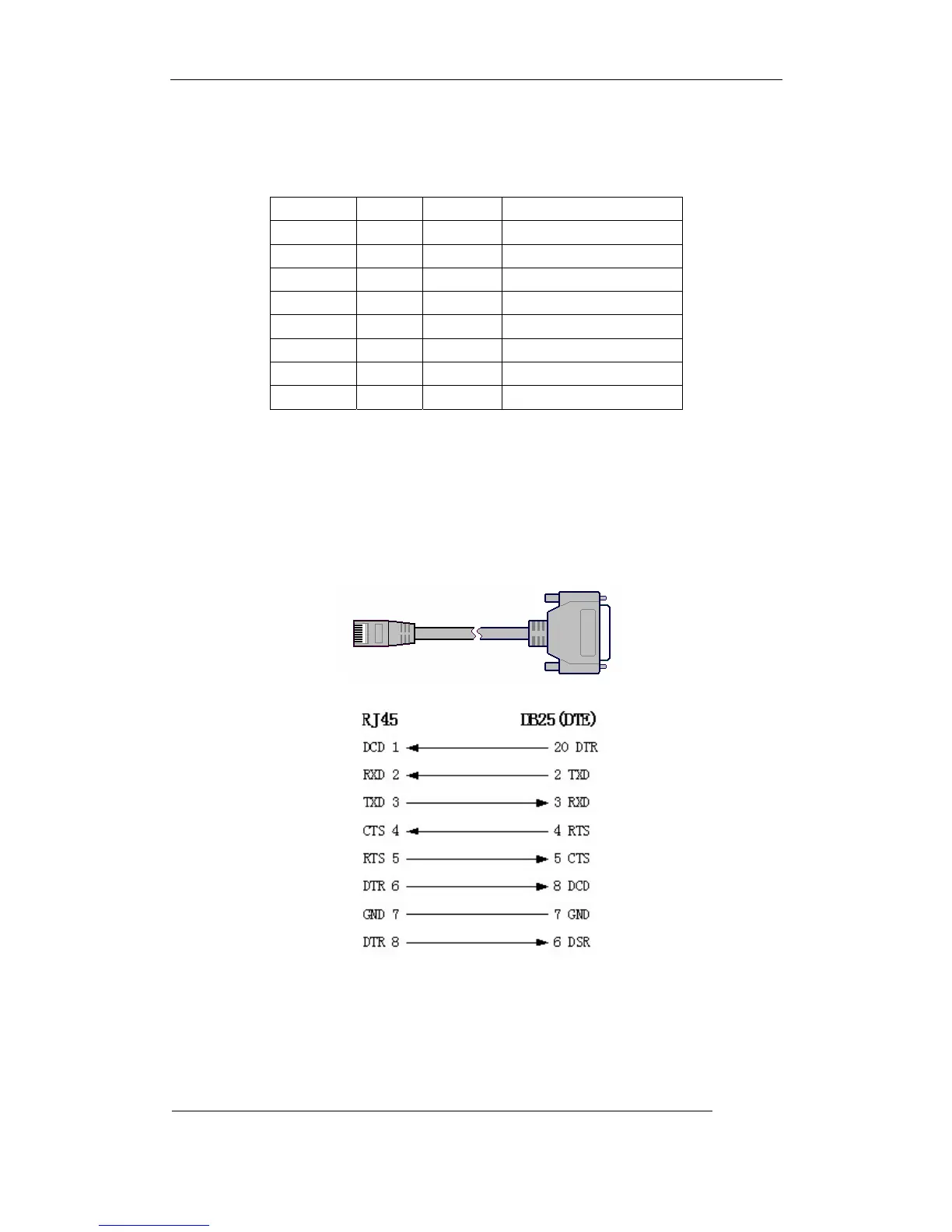
Pin definition
To make the RJ45 according to the following pin definition; I means DVR input, O means DVR
output.
Pin index Name I/O Description
1 DCD I Carrier Detect
2 RxD I Receive Data
3 TxD O Transfer Data
4 CTS I Clear Data
5 RTS O Request to Send
6 DTR O Terminal Device Ready
7 GND Ground
8 Null
— —
According to demand, the following three situations are considered to make the serial port
plug-in according to the corresponding relationship of the pin definition.
(1) When the serial port of the DVR is connected with the DTE device with DB25 plug-in
(terminal like computer, annunciator, door access etc), the corrresponding relationship is as
follows:
Connection for RJ45 and DB25 (DTE)
(2) When the serial port of the DVR is connected with DTE device with DB9 plug-in, the
corresponding relationship is as follows:
 Loading...