26
Installation EAGLE20/30
Release
06
04/2014
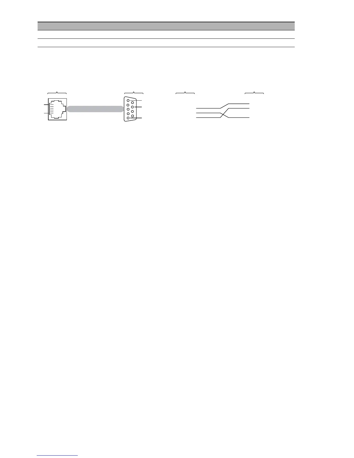
The socket housing is electrically connected to the front panel of the device.
The V.24 interface is electrically insulated from the working voltage.
Figure 1: Pin assignment of the V.24 interface and the DB9 connector
You find the order number for the terminal cable, which is available as
accessory, under “Accessories” on page 50.
1.8.2 SD card interface
Note: For information about the position on the device see “Rear view” on
page 21.
The SD card interface allows you to connect the AutoConfiguration Adapter
ACA31 storage medium. This is used for saving/loading the configuration
data and diagnostic information, and for loading the software.
The ACA31 supports the FAT16 file system format exclusively.
1.8.3 USB interface
Note: For information about the position on the device see “Front view” on
page 20.
The USB socket is an interface for the local connection of an
AutoConfiguration Adapter ACA21-USB. It is used for saving/loading the
configuration data and diagnostic information, and for loading the software.
The USB interface has the following properties:
Supports the USB master mode
Supports USB 1.1 (data rate max. 12 MBit/s)
Connectors: type A
Supplies current of max. 500 mA
Voltage not potential-separated
Supported file system format: FAT16
Handshake off
Parity none
VT 100 terminal settings
 Loading...