Installation EAGLE20/30
Release
06
04/2014
27
1.9 Input/output interfaces
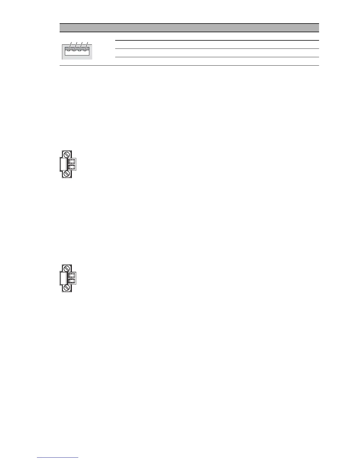
1.9.1 Signal contact
Figure 2: Signal contact: 2-pin terminal block with screw locking
In the state on delivery, the signal contact indicates the device status. It can
be configured using the device management.
1.9.2 Input
(no function in the existing device version)
Figure 3: Input: 2-pin terminal block with screw locking
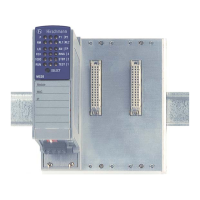
Figure Pin Operation
1 VCC (VBus)
2 − Data
3 + Data
4 Ground (GND)
Table 8: Pin assignment of the USB interface
1
2
4
3
 Loading...