3
/
6
ELECTRICAL WIRING
3.
ELECTRICAL WIRING
3.1.
STANDARD WIRING
Ô
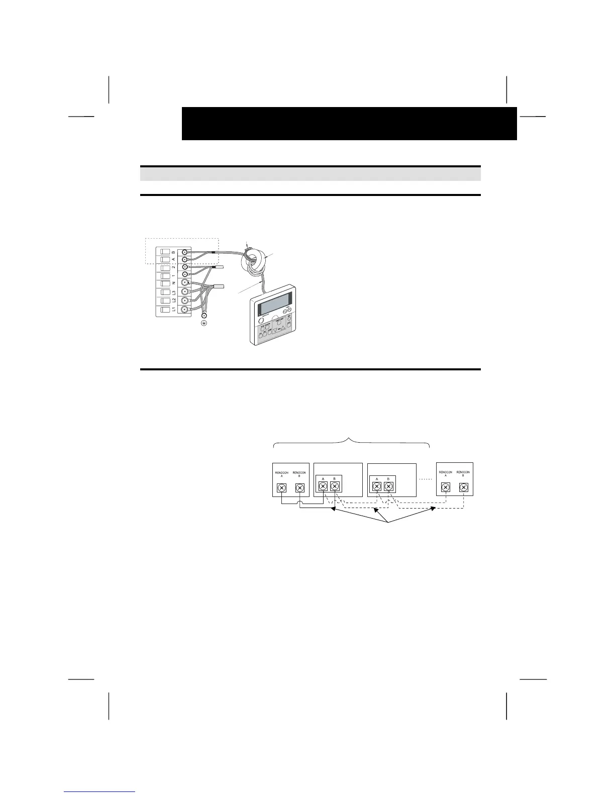
ATTENTION:
- Attach the ring core (black) (accessory)
when installing the unit.
- Insert the controller cable into the ring
core 2 turns as shown in the right figure
before connecting to the terminal board.
If wiring is 0.75 mm
2
is necessary to peel
the outside cover.
- Fix the cable by using the band
(accessory)
3.2.
ELECTRICAL WIRING FOR MULTIPLE UNITS
This remote control switch can
control sixteen units, as the
maximum.
In case of this modification,
wiring connection and other
works shall be performed as
indicated in the following
procedures.
Two Remote Controls can be
connected in the same unit or
unit groups. The second one is
Subsidiary Remote Control
Switch as indicated below.
Check Chapter 5 for more
information.
Controller
Ring core
Band
Controller
cable
Max. 16 Indoor Units
Remote Control
Switch
Electrical Box of
Indoor Unit
Electrical Box of
Indoor Unit
Remote
Control
Switch
(Subsidiary)
M3
Screws
M3 .5
Screws
M3 .5
Screws
Twist Pair cable: 2 x 0.75 mm

 Loading...


