Removing or Replacing the Camera
Note: It is recommended to remove the camera only when necessary. If disassembly is required please follow the
instructions and perform the removal and replacement in a clean indoor desktop environment.
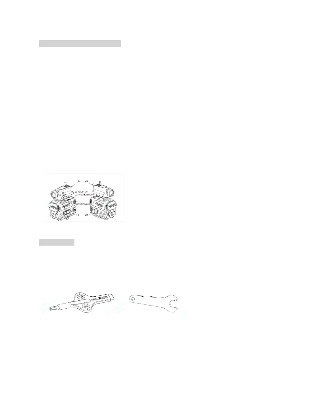
1. To remove the camera, use the included T10 tool to remove the four screws by rotating counterclockwise and
then remove the four screws 1 # ->2 # ->3 # ->4 # in sequence. Remove the camera installed on the upper part of
the red dot sight. Take note of the screw size difference between the front screws and rear screws.
2. Keep the connector contacts clean. Do not touch the contacts with your hands. If the contacts are accidentally
contaminated, use a clean alcohol cotton to wipe to clean the contacts several times.
3. Replace the camera seating it properly according to the locating pins. Then press the camera and lower housing
together, especially the conductive connection base, as vertically and tightly as possible to maintain pressure
between the camera and the lower housing. Use a T10 tool to reinstall the four screws. It is recommended to install
in this sequence: #4 ->#3 ->#2 ->#1. Lastly, tighten the screws in a crisscross pattern to 15 inch/Ibs, keeping the gap
between the camera and the body consistent as you tighten the screws. (As shown in Figure 12)
Figure 12
Included Tools:
1. T10 Torx tool with flat driver to adjust windage & elevation. (Figure 13)
2. 11mm Hex Wrench.
Figure 13
 Loading...