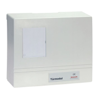
Mounting and Connection Instructions - Door module RS485 3
Inhaltsverzeichnis
1. General information ................................................................ 5
1.1 Performance features ......................................................... 5
1.2 Configuration ............................................................... 6
1.2.1 Example MultiAccess for Windows ........................................ 6
1.2.2 Example IQ MultiAccess ................................................ 7
2. Important installation instructions .................................................... 8
2.1 Protective measures during installation ........................................... 8
2.2 Grounding/shielding .......................................................... 8
2.3 Shielding and ground potential ................................................. 9
2.4 Interface technology, RS-485 bus systems ........................................ 9
2.6 Cable lengths/types ......................................................... 10
3. Power supply .................................................................... 10
3.1 Power supply unit ........................................................... 10
3.2 Directives for the power supply ................................................ 10
3.3 Battery .................................................................... 11
3.4 Integriertes Netzteil .......................................................... 11
3.4.1 Funktional description ................................................. 12
3.4.2 Adjusting the end-of-charging voltage .................................... 12
3.4.3 Connection/component mounting diagram ................................ 13
4. Mounting ........................................................................ 14
4.1 Mounting of Door module RS485 (026593.10) ..................................... 14
4.2 Mounting of Door module RS485 (026594.10) ..................................... 14
5. Technical data ................................................................... 15
5.1 Technical data 026593.10, Door module 12V DC, RS485 ........................... 15
5.2 Technical data 026594.10, Door module 230V AC, RS485 .......................... 15
6. General connection diagram ....................................................... 16
6.1 Description of fuse, jumpers and LEDs .......................................... 17
6.1.1 Fuse SI1 ............................................................ 17
6.1.2 Jumpers for level definition ............................................. 17
6.1.3 Jumpers for Cover contact / tear-off contact ............................... 17
6.1.4 Jumper for RS-485 interface ............................................ 17
6.1.5 Connection tamper contact reader (TC) ................................... 17
6.1.6 LEDs ............................................................... 17
6.1.7 DIP switch addresses ................................................. 18
6.1.8 Reader type and card coding ........................................... 19
7. Connecting a door strike .......................................................... 20
7.1 Connecting a door strike with load current function ................................ 20
7.2 Connecting a no-load current door strike ........................................ 20
8. Electric safety lock ............................................................... 21
8.1 Door monitoring ............................................................ 21
9. Connection diagram with Module potential separation ................................. 22
10. Connections ..................................................................... 23

 Loading...