Excel 800 Wiring and Setting Up the System
25 EN1B-0375GE51 R0910
Connecting Single Bus Controller Systems
This section describes how to connect a controller system
which uses Panel Bus I/O modules, only or L
ONWORKS
Bus I/O modules, only.
Controller and I/O Modules on a Single Rail
► Connect controller and I/O modules using the bridge
connectors.
This provides power supply and communication connection.
No further wiring is necessary.
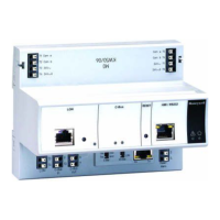
Controller and I/O Modules on Several Rails in a
Single Cabinet
The rails of a controller system are connected in series.
► Connect the rail ends as follows:
– Power supply
via power supply terminals 73, 74 or 77, 78
– Communication
via communication terminals 71, 72 or 75, 76
I/O
I/OI/O
I/O
I/O
I/O
I/O
I/O
I/O
75
75
71
71
71
71
76
76
72
72
72
72
77
77
73
73
73
73
78
78
74
74
74
74
CPU
1 2
Fig. 33 Wiring the power supply and the communication
lines to the I/O modules
Maximum Power Cable Length
The maximum length for power supply cable per side is 3 m.
This also includes the connection cables between the rails,
the lengths of the modules, and the cable from the
transformer.
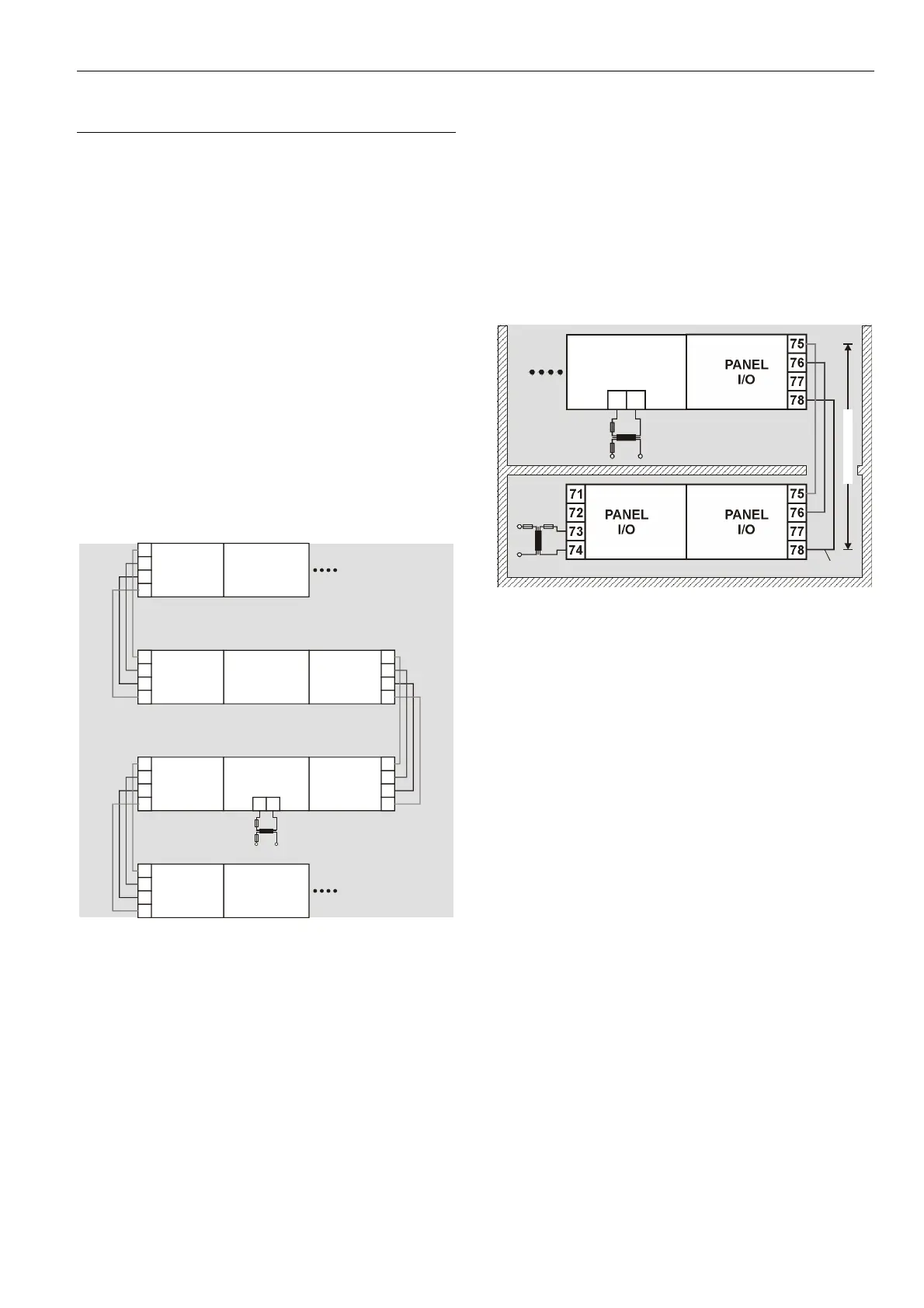
Panel Bus I/O Modules in Separate Rooms
In this scenario, communication and reference voltage
(24 V0) must be connected between the rooms.
► Connect the last module of room 1 to the first module of
room 2:
– Reference voltage
via power supply terminals 74 or 78
terminals 73 and 77 must not be connected
– Communication
via communication terminals 71, 72 or 75, 76
PANEL
I/O
PANEL
I/O
PANEL
I/O
75
75
71
76
7672
77
7773
78
78
74
MAX. 40 m
24 V0
CPU
1 2
Fig. 34 Wiring the Panel Bus I/O modules in separate
rooms
Maximum Cable Length
The maximum cable length for connecting room 1 and
room 2 is 40 m.
 Loading...