Excel 800 Description of the I/O Modules
57 EN1B-0375GE51 R0910
Floating Output Module
Features
Type: XFR825 Floating Output Module
Housing: light-gray
Floating outputs sufficient for driving up to 3 floating
actuators
Manual overrides and 3 corresponding pairs of status
LEDs
In the event of communication problems, the three floating
outputs will move to the safety positions you have
configured in CARE, see floating output point description in
the CARE – User Guide, EN2B-0182GE51 / 74-5587.
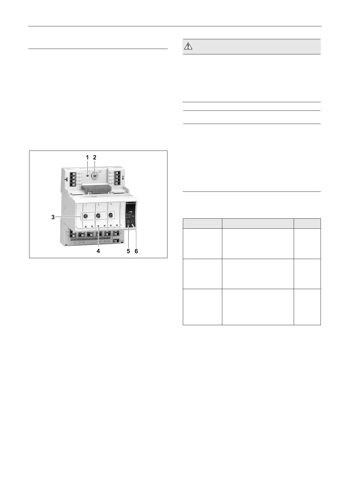
Fig. 81 XFR825 Floating Output Module with terminal
socket
Legend
1 Service button S1
2 Hex switch S2
3 Manual overrides
4 Status LEDs
5 Service LED
6 Power LED
Functionality of service LED and power LED: see Table 77
to Table 79 on page 77 and following.
WARNING
Risk of electric shock or equipment damage!
Low voltage and line voltage must not be wired within
the same relay block.
► Wire low voltage e.g., to relay block 1 and line voltage to
relay block 2 or vice versa. In this case, the short cross
connectors must be used, see Table 5 on page 7.
NOTICE
Risk of malfunction!
Cross connectors may only be used if the same voltage
is used on all relays they connected.
► Do not use a cross connector if different voltages are
used on the relays.
E.g., use a short cross connector for relay block 1 with
line voltage and no cross connector for relay block 2 with
12 V low voltage for relay 4 and 24 V low voltage for
relays 5 and 6.
Permissible Loads
Max. load Min. load
Per relay
output
module (total)
19…250 VAC
current at cos φ ≥ 0.6: 12 A
1…29 VDC
12 A resistive, 3 A inductive
–
Per normally
open contact
19…250 VAC
current at cos φ ≥ 0.6: 4 A)
1…29 VDC
4 A resistive, 1 A inductive
50 mW
Per normally
closed
contact
19…250 VAC
current at cos φ ≥ 0.95: 2 A,
current at cos φ ≥ 0.6: 1 A
1…29 VDC
4 A resistive, 1 A inductive
50 mW
Table 57 Permissible loads of floating output modules
Notes
In the case of voltages above 30 VAC/DC and if inductive
components are to be connected to relays switching
more often than once every 2 minutes, these com-
ponents must be prevented from causing harmful
interference to radio or television reception (conformance
with EN 55014).
Max. voltage for UL 864-compliant applications is 24 V.
 Loading...