Excel 800 Description of the I/O Modules
49 EN1B-0375GE51 R0910
Binary Input Modules
Types of Binary Input Modules, Terminal Socket
Type Description Housing
XF823 Panel Bus binary input module Light-gray
XFL823
L
ONWORKS Bus binary input
module
Dark-gray
XS823
XSU823
Terminal socket Light-gray
Table 50 Excel 800 Binary Input Modules
Features
12 binary inputs
12 configurable status LEDs (green/red, yellow/OFF)
Binary inputs can be used as
– Static digital inputs as dry-contacts (default)
– Fast totalizers (up to 20 Hz)
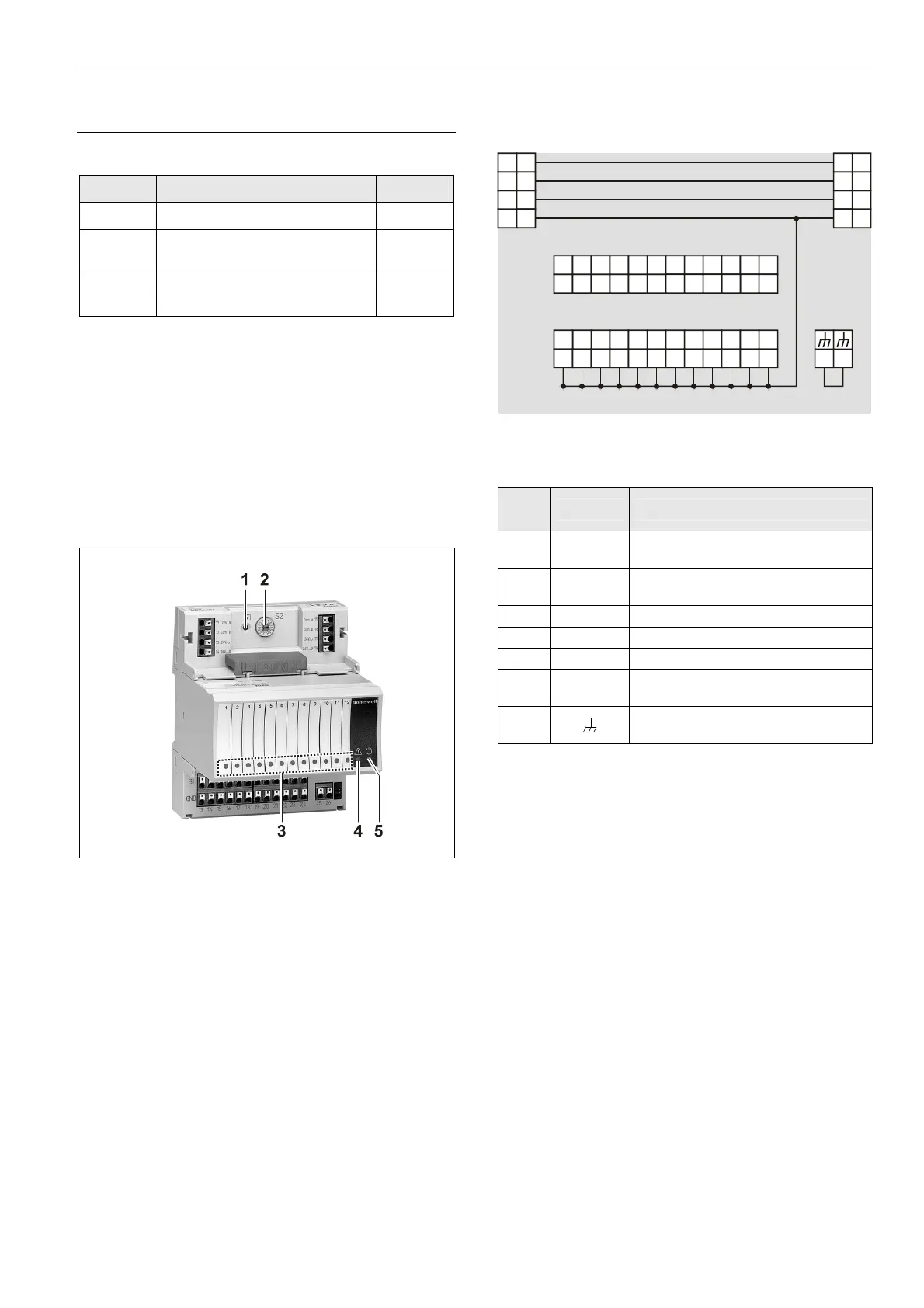
Fig. 72 XF823 Binary Input Module with terminal socket
Legend
1 Service button S1
2 Hex switch S2
3 Status LEDs
4 Service LED
5 Power LED
Functionality of service LED and power LED: see Table 77
to Table 79 on page 77 and following.
Terminals
74
78
73 77
72
76
71
75
24
V
~
24
V
~
24
V
~
0
24
V
~
0
COM
B
COM
B
COM
A
COM
A
1 2
3
4
5
6
BI1 BI2
BI3
BI4
BI5 BI6
BI7
BI8 BI9
BI10
BI11BI12
7 8
GNDGNDGND GND GND GND GND GND GND GND GND GND
11
109
12
13
14
15 16
17
18 19 20
21 22
23
24
25 26
Fig. 73 Terminal assignment and internal connections of
binary input modules
Ter-
minal
Signal COMMENT
71, 75 COM a
2-wire communication bus
(LON/Panel Bus)
72, 76 COM b
2-wire communication bus
(LON/Panel Bus)
73, 77 24 V~ Power supply
74, 78 24 V~0 Power supply
1…12 BI1…BI12 Binary inputs 1…12
13…24 GND
Ground. All grounds are internally
connected to each other.
25, 26
Shield connection (functional earth),
internally connected to the DIN rail.
Table 51 Description of binary input module terminals
Notes
Shield connection to be used for shielded I/O cables only.
It is not allowed to connect a L
ONWORKS shield, since
L
ONWORKS requires a resistor and capacitor.
If additional shield terminals are needed, the
XS814 Auxiliary Terminal Package can be installed.
 Loading...