Description of the I/O Modules Excel 800
EN1B-0375GE51 R0910
44
Analog Output Modules
Types of Analog Output Modules, Terminal Socket
Type Description Housing
XF822
Panel Bus analog output
module
Light-gray
XFR822
Panel Bus analog output
module with manual overrides
Light-gray
XFL822
L
ONWORKS Bus analog output
module
Dark-gray
XFLR822
L
ONWORKS Bus analog output
module with manual overrides
Dark-gray
XS821-22
XSU821-22
Terminal socket Light-gray
Table 46 Excel 800 analog output modules
Features
8 analog outputs;
can also be configured per output as binary outputs
(0 … 10 V, 2 … 10 V, ON/OFF, or floating)
Corresponding status LEDs (red)
…R822: 8 manual overrides, see figure below
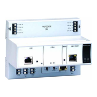
Fig. 66 XF822 Analog Output Module with terminal
socket
Legend
1 Service button S1
2 Hex switch S2
3 Manual overrides
4 Status LEDs
5 Service LED
6 Power LED
Functionality of service LED and power LED: see Table 77
to Table 79 on page 77 and following.
In the event of communication problems, the analog outputs
will move to the safety positions you have configured in
CARE, see analog output point description in the CARE –
User Guide, EN2B-0182GE51 / 74-5587.
Terminals
74
78
73 77
72
76
71
75
24
V
~
24
V
~
24
V
~
0
24
V
~
0
COM
B
COM
B
COM
A
COM
A
1 2
3
4
5
6
AO1AO2AO3AO4 AO5AO6 AO7AO8
7 8
GNDGNDGND GND GND GND GND GND GND GND
11
109
12
13
14
15 16
17
18 25 26
21
NC NC
22
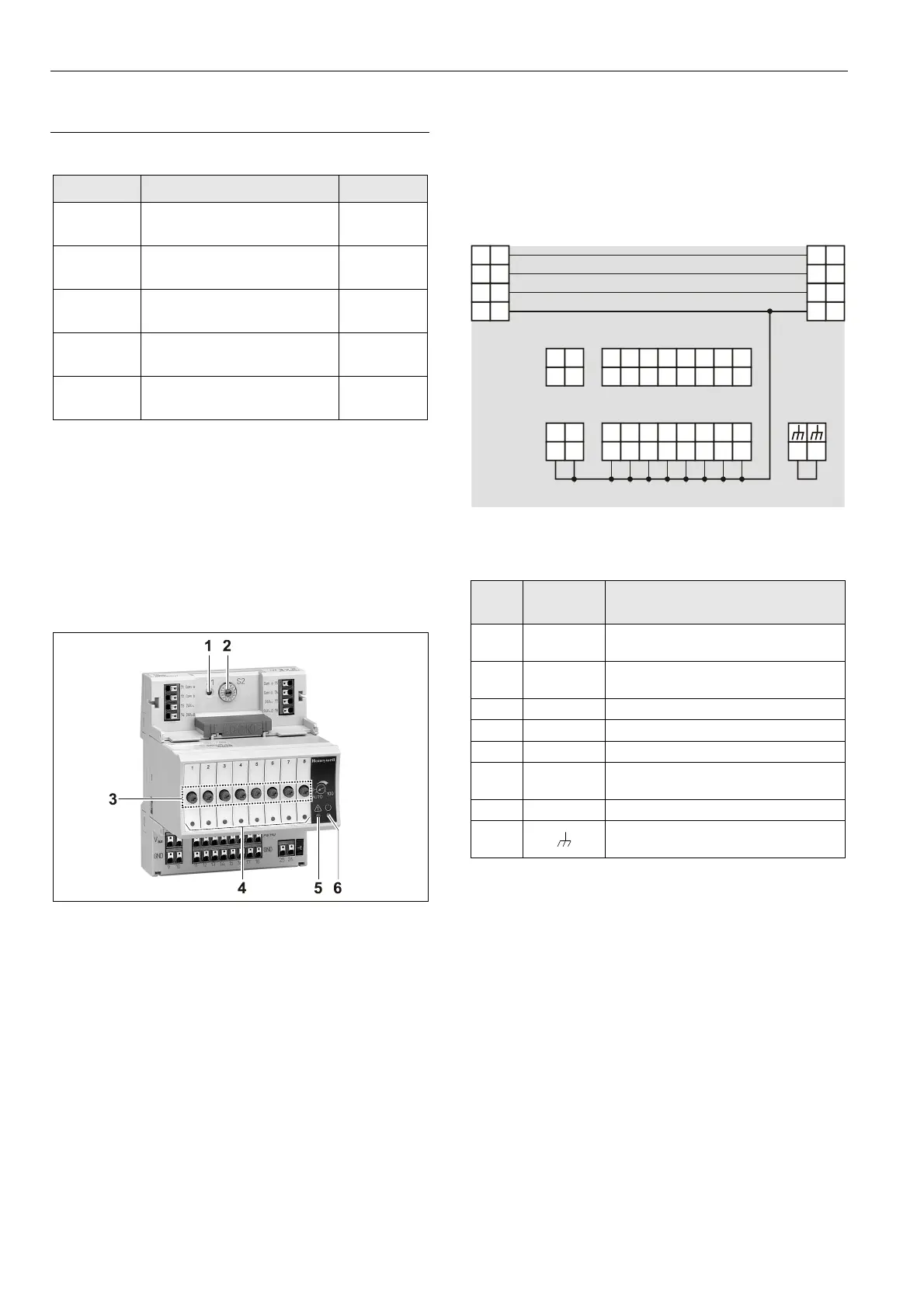
Fig. 67 Terminal assignment and internal connections of
the analog output modules
Ter-
minal
Signal COMMENT
71, 75 COM a
2-wire communication bus
(LON/Panel Bus)
72, 76 COM b
2-wire communication bus
(LON/Panel Bus)
73, 77 24 V~ Power supply
74, 78 24 V~0 Power supply
1…8 AO1…AO8 Analog outputs 1…8
9…18 GND
Ground. All grounds are internally
connected to each other.
21, 22 N.C. Do not use!
25, 26
Shield connection (functional earth),
internally connected to the DIN rail
Table 47 Description of the analog output module terminals
Notes
Shield connection to be used for shielded I/O cables only.
It is not allowed to connect a L
ONWORKS shield, since
L
ONWORKS requires a resistor and a capacitor.
If additional shield terminals are needed, the
XS814 Auxiliary Terminal Package can be installed.
 Loading...