Description of the I/O Modules Excel 800
EN1B-0375GE51 R0910
58
Terminals
74
78
73 77
72
76
71
75
24
V
~
24
V
~
24
V
~
0
24
V
~
0
COM
B
COM
B
COM
A
COM
A
13 4323 5333 63
12 4222
5232 62
NO NONO NONO NO
NC NCNC NCNC NC
COM COMCOM COMCOM COM
11 4121
5131 61
ACTUATOR 1 ACTUATOR 3ACTUATOR 2
25
CROSS CONNECTOR (REMOVABLE)
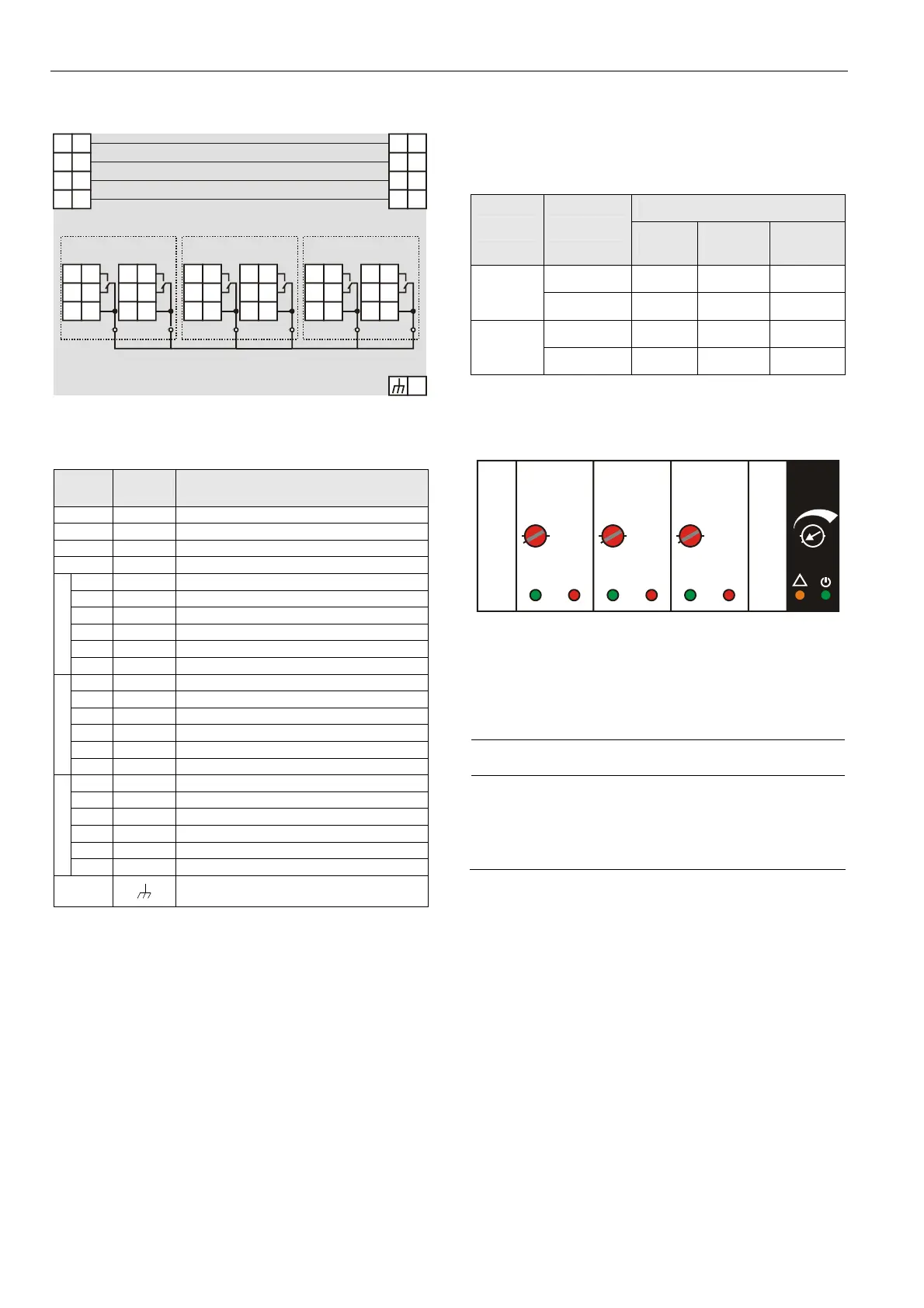
Fig. 82 Terminal assignment and internal connections of
floating output module
Ter-
minal
Signal Comment
71, 75
COM a
2-wire communication bus (LON/Panel Bus)
72, 76
COM b
2-wire communication bus (LON/Panel Bus)
73, 77
24 V~
Power supply
74, 78
24 V~0
Power supply
11
REL1 N.O.
Floating relay 1 N.O. contact
12
REL1 N.C.
Floating relay 1 N.C. contact
13
R1 COM
Floating relay 1 common contact
21
REL2 N.O.
Floating relay 2 N.O. contact
22
REL2 N.C.
Floating relay 2 N.C. contact
ACTUATOR 1
23
R2 COM
Floating relay 2 common contact
31
REL3 N.O.
Floating relay 3 N.O. contact
32
REL3 N.C.
Floating relay 3 N.C. contact
33
R3 COM
Floating relay 3 common contact
41
REL4 N.O.
Floating relay 4 N.O. contact
42
REL4 N.C.
Floating relay 4 N.C. contact
ACTUATOR 2
43
R4 COM
Floating relay 4 common contact
51
REL5 N.O.
Floating relay 5 N.O. contact
52
REL5 N.C.
Floating relay 5 N.C. contact
53
R5 COM
Floating relay 5 common contact
61
REL6 N.O.
Floating relay 6 N.O. contact
62
REL6 N.C.
Floating relay 6 N.C. contact
ACTUATOR 3
63
R6 COM
Floating relay 6 common contact
25
Shield connection (functional earth),
internally connected to the DIN rail
Table 58 Description of floating output module terminals
Status LED Behavior
The respective pair of status LEDs will display the following
behavior:
Actuator 1
Mode LED
Closing Opening
Not
moving
Green LED ON OFF OFF
Auto
Red LED OFF ON OFF
Green LED Flashing OFF Flashing
Override
Red LED OFF Flashing Flashing
Table 59 LED behavior (for e.g., floating output 1)
Status LEDs with Manual Overrides
1
2
3
Honeywell
AUTO
0
!
100
Fig. 83 Manual overrides (rotary knobs)
The floating output module is equipped with manual
overrides: one for each floating output. These rotary knobs
can be manually set to either "AUTO" or "0 … 100%"
(infinitely adjustable).
NOTICE
Damage to the electronic module!
► Do not use a tool to adjust the rotary knobs.
► Do not use excessive force. Adjust only by hand.
Manual Override in the AUTO Position
When a manual override of the XFR825 is set to AUTO, the
following applies:
The output signal of the respective floating output (R1 +
R2 or R3 + R4 or R5 + R6) will be as commanded.
The respective pair of status LEDs will be ON/OFF as
commanded.
Manual Override in the Override Position (0…100%)
When a manual override of the XFR825 is set to 0…100%,
the respective floating output will drive to the set position.
The runtime depends upon the actuator runtime configured
in CARE and on the actual position.
 Loading...