Excel 800 Troubleshooting
79 EN1B-0375GE51 R0910
LED Test for I/O Modules (pluggable I/O modules, only)
► Press the service button S1 of the pluggable I/O module, e.g. using a paperclip.
– The service LED and all other LEDs of that Panel Bus I/O module light up for as long as the service button is pressed.
LED Correct behavior
Power LED ON continuously (if it flashes, check the 24 VAC power supply)
Service LED ON continuously
Analog output module status LEDs ON continuously
Relay output module status LEDs ON continuously
Digital input module status LEDs Red -> green -> yellow -> red -> green -> yellow, cyclically every 0.5 sec
Table 79 Effects of pressing and holding down service button of pluggable I/O modules
An LED is defective if it is not lit as shown above.
Analog Input Modules Troubleshooting
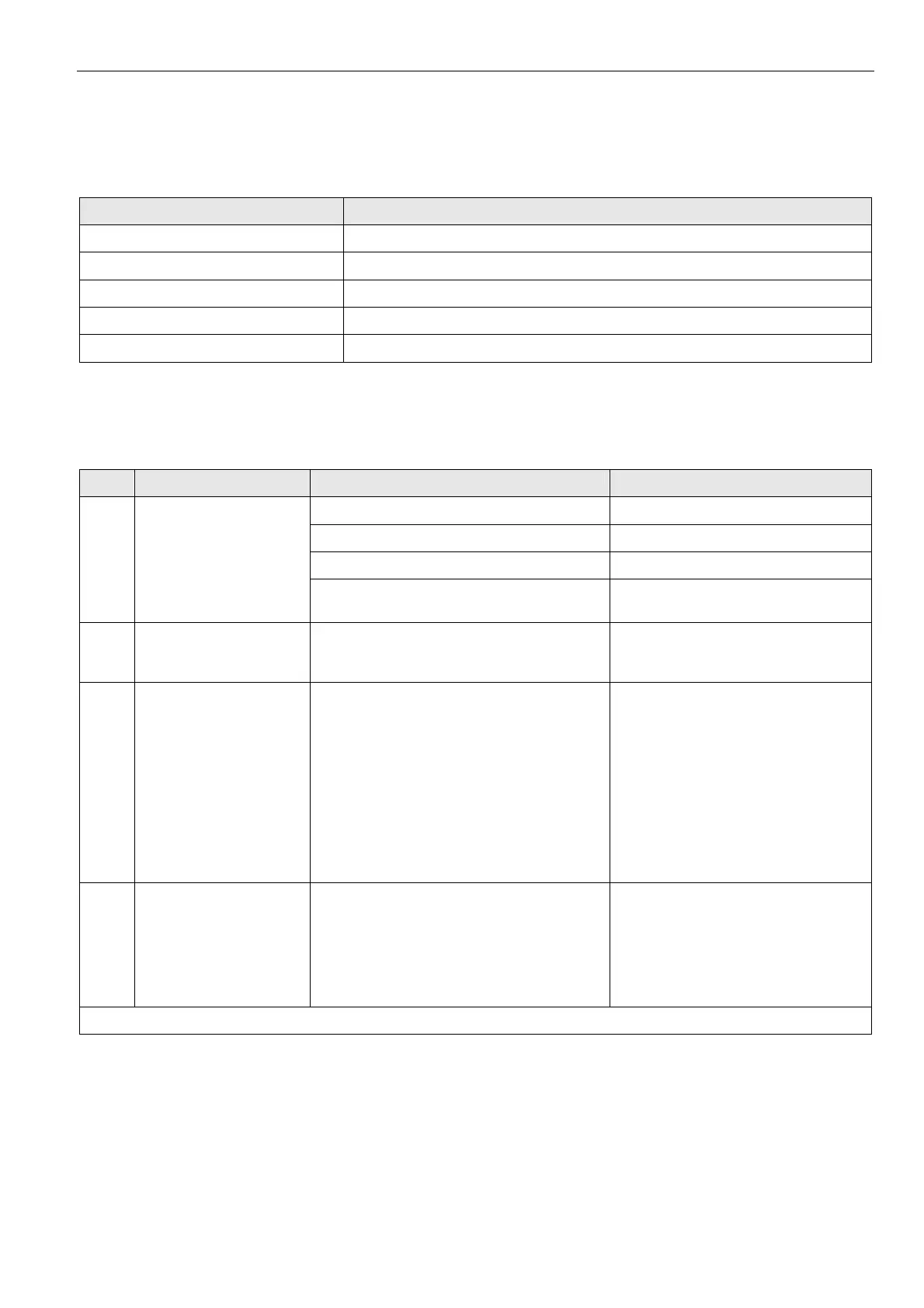
case Problem Possible causes Remedy
Wrong sensor configuration
► Reconfigure sensor
Incorrect wiring
► Rewire
Sensor failure
► Replace sensor
1
Incorrect sensor
measurement
Negative voltage on at least one channel
► Check polarity of active sensor
inputs.
2
Unstable sensor
measurements
Incorrect grounding of active sensors
► Ground active sensors individually
(see Fig. 64 and Fig. 65 on page 42
and following)
3
a voltage of about
8.88 V(*) is measured
(with an external volt-
meter) at an open analog
input configured for:
NTC20kΩ or
Pt1000-1/-2 or
Pt3000 or
Balco 500 or
NTC10kΩ or
NI1000TK5000.
Sensor is not connected
► Connect the configured sensor
4
a voltage of about
8.88 V(*) is measured
(with an external volt-
meter) at an open analog
input configured for:
0…10V with pull-up or
slow Digital Input
Normal value for open input that is configured
to listed types
► No action necessary
(*): voltage may differ slightly depending on the input impedance of the used voltmeter
Table 80 Failure modes of analog input modules
 Loading...