System Overview LED Indicators
10 HPFF8(E)/HPFF8CM(E) NAC Expander — P/N 53499:B4 10/1/2018
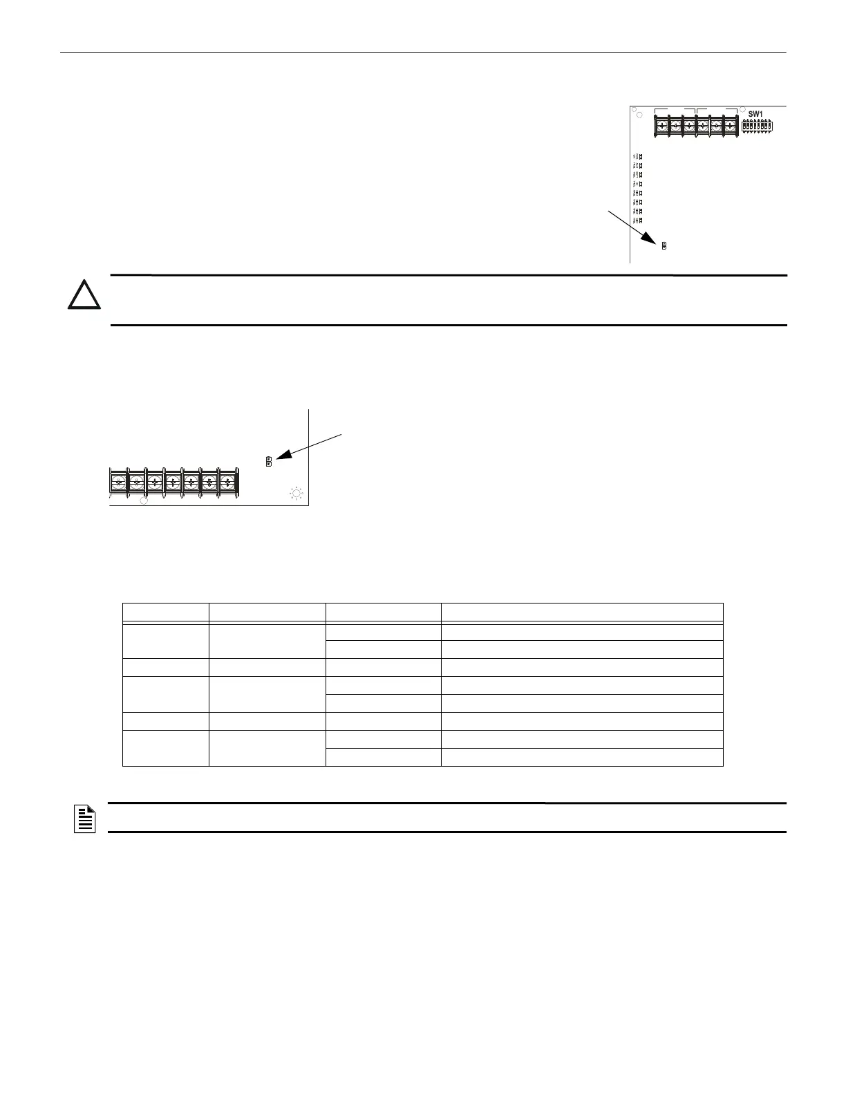
1.4.1 Charger Disable Jumper (J1)
The HPFF power supplies’ battery charger capacity is 26 AH maximum using the integral char-
ger with a maximum charging rate of 0.75 A. The integral charger on the Control circuit board
must be disabled in certain situations by removing the charger-disable jumper. One situation is
when system requires a common battery set, as is possible in the large equipment enclosure.
Another situation is if the system requires a larger battery capacity than the integral charger can
charge in the proper time. Larger capacity batteries can be used if they are housed in an external
UL-Listed enclosure, along with a UL-Listed battery charger that can restore the full charge to
the batteries in the proper time.
Larger capacity batteries can be used if they are housed in an external UL-Listed enclosure, along with a UL-Listed battery charger suit-
able for fire alarm service and with sufficient capacity to restore the full charge in the required time. The alternate enclosure and battery
charger shall be listed for Fire Protective Signaling use.
1.4.2 Ground Fault Disable Jumper (J2)
The Ground Fault detection circuit on the Control circuit board monitors the impedance
from earth ground to any user wiring point, including +24 VDC. An exception is the
initiating device signal inputs because they are optically-isolated from the rest of the
circuitry and should be detected by the initiating device or FACP. Remove ground-fault
disable jumper to disable the ground fault detection.
If the common circuitry of two or more HPFFs are connected together, or if the com-
mon of an HPFF is connected to the common of a system, such as a single battery con-
nected to multiple units, then the ground fault jumpers must be removed from all but
one of the units. The unit with the jumper installed provides the ground monitoring for
the whole system. If two or more units are connected together with ground fault monitoring enabled, then the monitoring circuits inter-
fere with each other, and false ground faults will be generated.
1.5 LED Indicators
1.6 Specifications
Refer to Figure 1.1 and Figure 1.2 on page 12 for terminal locations.
Primary AC Power — TB1 (on 24 VDC power-supply circuit board)
• HPFF8 and HPFF8CM: 120 VAC, 60 Hz, 3.6 A
• HPFF8E and HPFF8CME: 240 VAC, 50 Hz, 2.1 A
• Wire size: 14AWG (2.08 mm
2
) with 600 V insulation
Initiating Device Signal Inputs — TB3 (on Control circuit board); terminals SIGNAL1: +IN, –IN, +OUT, –OUT, and SIGNAL2:
+IN, –IN, +OUT, –OUT
• Supervised by FACP or initiating device, power-limited
• A supervisory relay must be used if initiating device is a power source
N/O
N/C
COMM
N/O
N/C
COMM
AC FAIL
TROUBLE
J1
CAUTION: BATTERY CHARGER DISABLED
THE BATTERY CHARGER IS AUTOMATICALLY DISABLED DURING ALARM, SO BATTERIES WILL NOT BE
CHARGED WHEN THE POWER SUPPLY IS IN THE ALARM STAGE.
J2
1L2 2L1 2L2
3L1 3L2
4L1 4L2
Indicator Name State Trouble Condition
LED 1, 2, 3, 4 SIG(1, 2, 3, 4) TRBL
Blinking NAC Trouble Memory
Steady illumination Open or shorted NAC
LED 5 GF TRBL Steady illumination An earth ground fault is present
LED 6 BAT TRBL
Blinking Charger Fault
Steady illumination Low or missing battery
LED 7 AUX TRBL Steady illumination Excessive loading or shorted auxiliary output
LED 8 POWER ON
Blinking Low (brownout) or missing AC input
Steady illumination Normal/Standby
Table 1.1 LED Indicators
NOTE: If all four SIG TRBL LEDs are illuminated steady, check if the reference ELR resistor is missing or doesn’t match the ELR resistors
used to terminate the Class B circuits. Otherwise, each NAC must have a trouble.
 Loading...


