Power-Limited Wiring Requirements Installation
HPFF8(E)/HPFF8CM(E) NAC Expander — P/N 53499:B4 10/1/2018 25
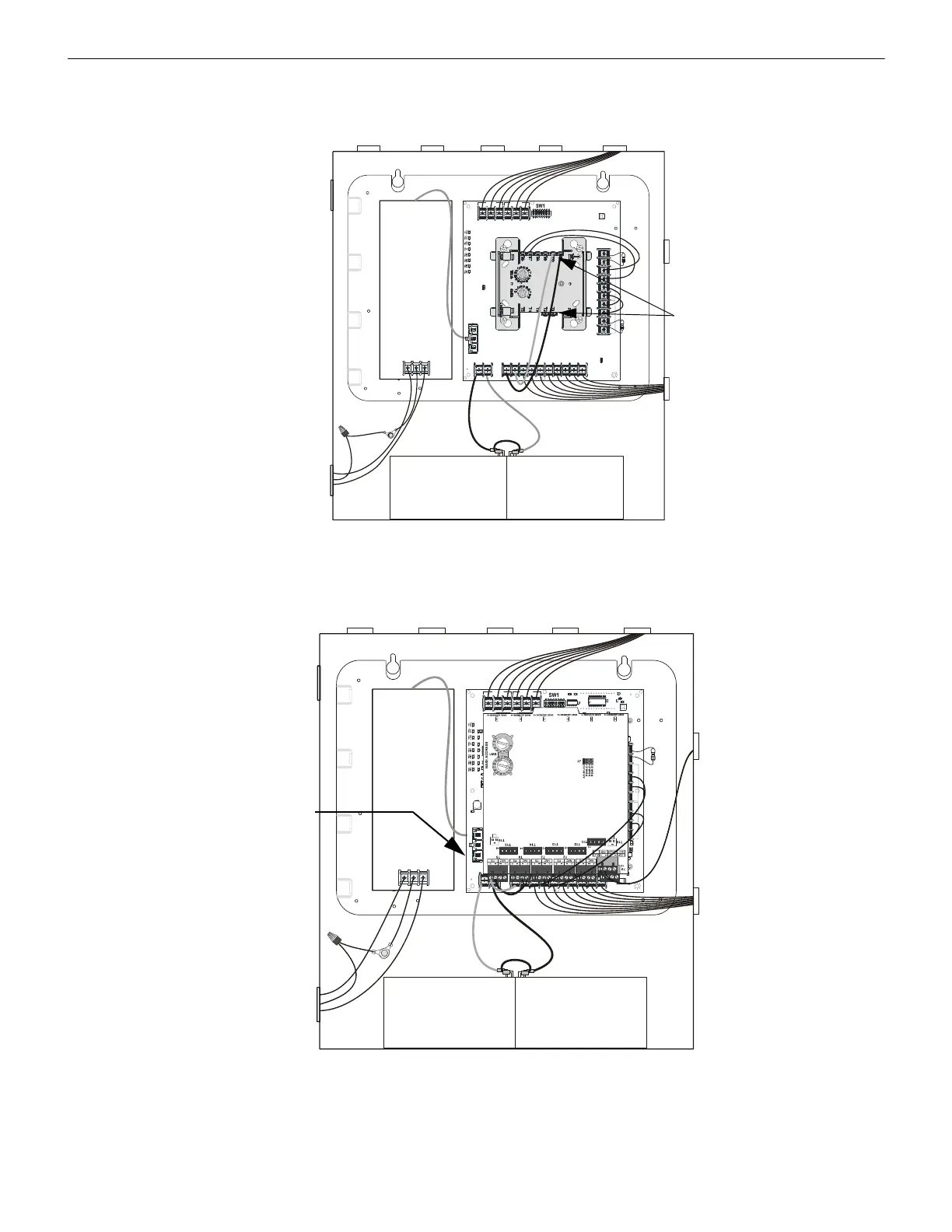
2.6.1 Power-Limited Wiring, Standard Chassis
TB3
TB4TB1
TB2
SW2
LEDs
REF+ REF– + IN – IN + OUT – IN + OUT+ OUT + IN – OUT
SIGNAL 1
SIGNAL 2
BATT+ BATT–
A+
N/O
N/C COMM
N/O
N/C COMM
AC FAIL
TROUBLE
J1
J2
1L1 1L2 2L1 2L2 3L1 3L2 4L1 4L2A–
Input Circuits
Power-limited
Special Application
Power & SLC are
power-limited
Output Circuits
Power-limited
AC Circuits
Nonpower-limited
Relay Contacts
Nonpower-limited
f
f
8
m
n
t
p
w
r
l
i
m
.
w
m
f
Battery connections
Nonpower-limited
Figure 2.16 Power-Limited Wiring Example: Single-input Control Module
TB3
TB4TB1
TB2
SW2
LEDs
REF+ REF– + IN – IN + OUT – IN + OUT+ OUT + IN – OUT
SIGNA L 1
SIGNAL 2
BATT+ BATT–
A+
N/O
N/C
COMM
N/O
N/C
COMM
AC FAIL
TROUBLE
J1
J2
1L1 1L2 2L1 2L2
3L1 3L2
4L1 4L2A–
Input Circuits
Power-limited
Special Application Power &
SLC are power-limited
Output Circuits
Power-limited
AC Circuits
Nonpower-limited
Relay Contacts
Nonpower-limited
f
f
8
m
n
t
p
w
r
l
i
m
6
u
p
.
w
m
f
Battery connections
Nonpower-limited
Maintain vertical separation
where power-limited and
nonpower-limited circuits
appear close together.
Figure 2.17 Power-Limited Wiring Example: Multi-Module
 Loading...


