Installation Power-Limited Wiring Requirements
24 HPFF8(E)/HPFF8CM(E) NAC Expander — P/N 53499:B4 10/1/2018
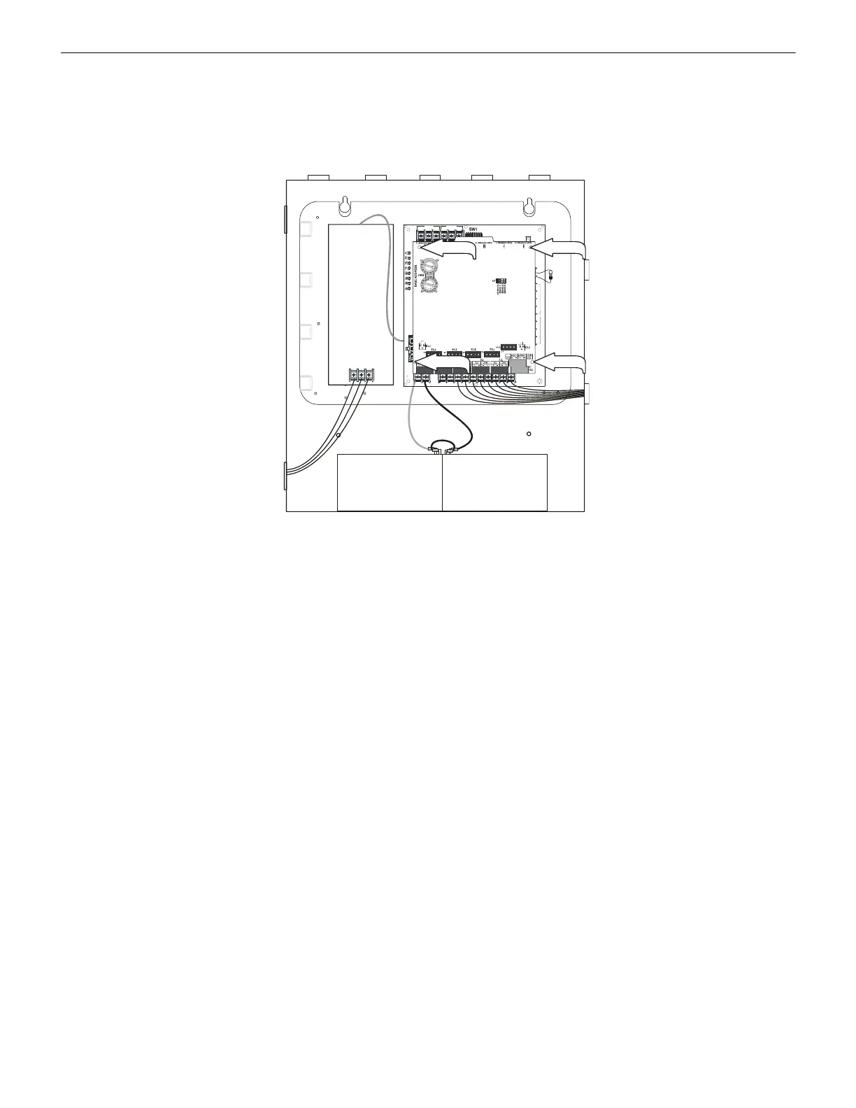
2.5.2 Mounting Six-Circuit Modules from Honeywell Fire Systems
Six-output addressable modules can be mounted directly to the control circuit board as shown in Figure 2.15 for the wall cabinet. This
allows wiring to remain in the cabinet. However, the six-output module cannot be mounted as shown in the HPFF8CM or HPFF8CME's
units when used in the large equipment enclosure. An optional multi-module chassis is available from Honeywell Fire Systems.
See Section 2.6, “Power-Limited Wiring Requirements”.
2.6 Power-Limited Wiring Requirements
Power-limited and nonpower-limited circuit wiring must remain separated in the cabinet. All power-limited wiring must remain at least
0.25" away from any nonpower-limited circuit wiring. Furthermore, all power-limited circuit wiring and nonpower-limited circuit wiring
must enter and exit the cabinet through different conduits. An example of this is shown below. Your specific application may require dif-
ferent conduit knockouts to be used in the standard cabinet. Any conduit knockouts may be used. For power-limited applications, use of
conduit is optional.
Connect the incoming earth ground wire to supplied cable #71073 with a wire nut. Position the ring terminal end over the grounding
stud. Secure with one of the keps nuts. Place the ring terminal from the other supplied ground cable #71073 over the ground stud and
secure with the second keps nut. Wire the ground cable to the middle position of TB1 on the 24VDC power supply circuit board. This
connection is vital in reducing the panel’s susceptibility to transients generated by lightning and electrostatic discharge. Apply AC power
to the panel only after the system is completely installed and visually checked. Note that AC power must be applied to the panel before
installing the battery interconnect cable.
TB3
TB4TB1
TB2
SW2
LEDs
REF+ REF– + IN – IN + OUT – IN + OUT+ OUT + IN – OUT
SIGNAL 1
SIGNAL 2
BATT+ BATT–
A+
N/O
N/C COMM
N/O
N/C COMM
AC FAIL
TROUBLE
J2
1L1 1L2 2L1 2L2
3L1 3L2
4L1 4L2A–
Figure 2.15 Mounting Details for Six-Output Modules from Honeywell Fire Systems
F
F
8
1
2
m
n
t
6
u
p
.
w
m
f
standoff standoff
standoff
standoff
 Loading...


