NAC Circuit Wiring Installation
HPFF8(E)/HPFF8CM(E) NAC Expander — P/N 53499:B4 10/1/2018 21
2.4.3 Mixing Class B and Class A NACs
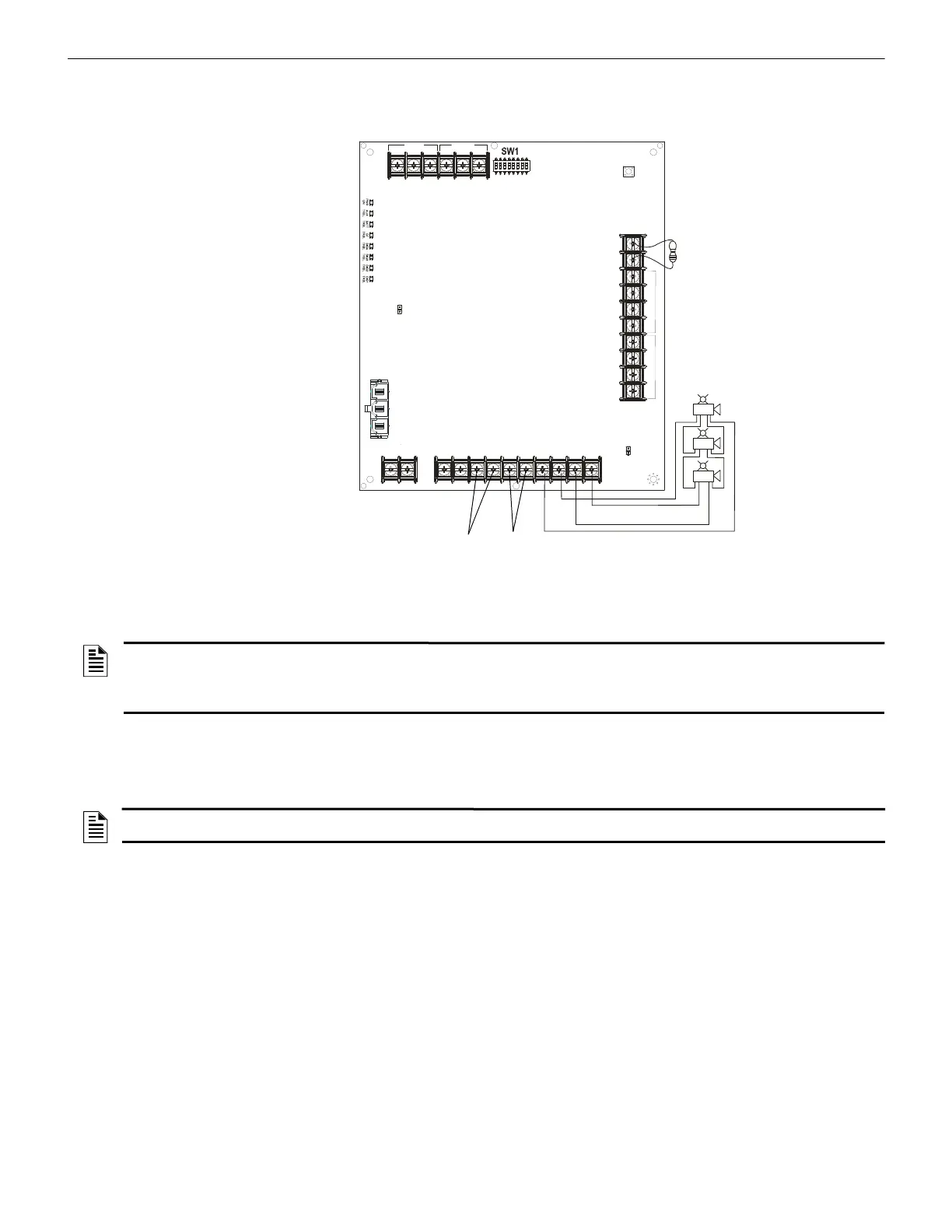
Figure 2.12 shows two NACs configured for Class B (Style Y) and one NAC configured for Class A (Style Z).
2.4.4 HPP31076 Optional Class A (Style Z) Adapter
The HPP31076 is an optional adapter to connect four Class A (Style Z) NAC circuits. It mounts directly onto the terminal block TB4 of
the Control circuit board. The adapter kit includes two plastic standoffs to provide support. The same gauge wire must be used if two
conductors are connected to the same terminal of any terminal block.
-
+
-
+
-
+
-
+
TB3
TB4
TB1
TB2
SW2
LEDs
REF+ REF– + IN – IN
+ OUT
– IN
+ OUT+ OUT
+ IN
– OUT
SIGNAL 1
SIGNAL 2
BATT+ BATT–
A+
N/O
N/C
COMM
N/O
N/C
COMM
AC FAIL
TROUBLE
J1
J2
1L1 1L2 2L1 2L2
3L1 3L2
4L1 4L2A–
NAC 1 and NAC 2 in Class B (Style Y)
- See Figure 2.10 for wiring.
NAC 3
f
f
8
1
2
n
a
c
c
l
a
s
s
A
B
.
w
m
f
Horn Strobe
Horn Strobe
Horn Strobe
Alarm Polarity
Shown
No ELR required for
NAC 3 in Class A.
NAC 1
• Trouble on NAC1 will illuminate
LED1 SIG1 TRBL
• Trouble on NAC2 will illuminate
LED2 SIG2 TRBL
• Trouble on NAC3 will illuminate
LED3 SIG3 TRBL and
LED4 SIG4 TRBL
Reference Resistor (Same as
ELRs for NAC 1 & NAC2)
NAC 2
Figure 2.12 Configuring Two Class B NACs and One Class A NAC on One HPFF8
NOTES:
1. Typical ELRs for new installations can be 3.9k or 4.7k ohm.
2. The same gauge wire must be used if two conductors are connected to the same terminal of any terminal block.
3. Do not complete a continuous circuit around the screw terminal. There must be two separate wires on either side of the screw at the
terminal block. “T-tapping” is absolutely NOT ALLOWED.
NOTE: Only use batteries with a maximum height of 4 inches in applications that require this adapter in the standard enclosure.
Otherwise, there is insufficient space to connect NAC field wiring, and a separate NFPA and UL 864 rated enclosure is required.
 Loading...


