28 HPFF8(E)/HPFF8CM(E) NAC Expander — P/N 53499:B4 10/1/2018
Section 3: Programming Options
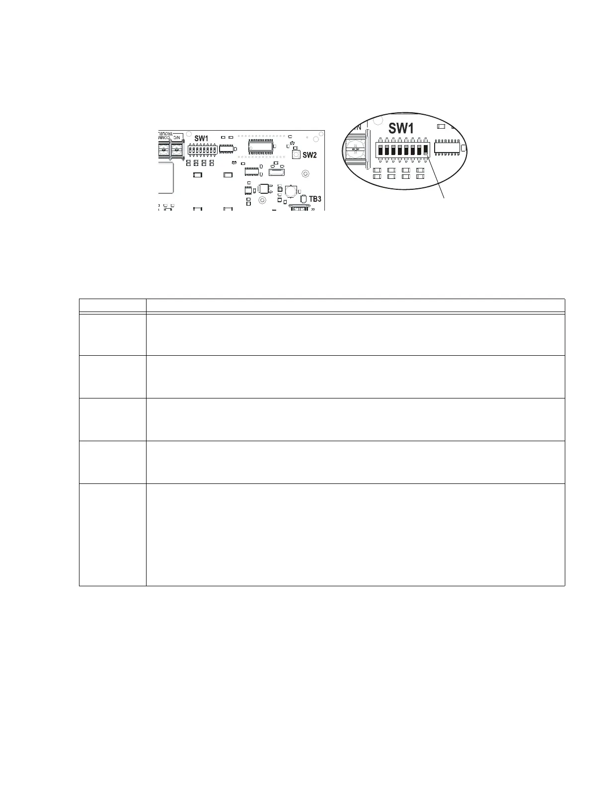
This section describes the programming options available via DIP switch settings. The HPFF can be field-programmed using DIP switch
SW1 on the Control circuit board. Refer to the following illustration for switch location and DIP switch settings for ON and OFF posi-
tions.
3.1 DIP Switch Settings
The following table lists the programmable features and the switch settings required to select a particular feature. A detailed description
of each is presented in the following pages.
Switches 2-7
shown in OFF position
Switch 1
shown in ON position
H
P
F
F
8
1
2
-
s
w
1
.
w
m
f
Figure 3.1 Field-Programming DIP Switches
SW1 DIP Switch
1 SIG 1/2 “A”
2 SIG 1/2 “A”
1 OFF, 2 OFF = Pass-through (Slave) (of Steady On, sync, or coded; DO NOT use with full-wave rectified input).
1 ON, 2 OFF = Temporal.
1 OFF, 2 ON = Sync generator (see switches 5 & 6).
1 ON, 2 ON = Pass-through (Slave) Filtered (use for full-wave rectified inputs).
3 SIG 3/4 “B”
4 SIG 3/4 “B”
3 OFF, 4 OFF = Pass-through (Slave) (of Steady On, sync, or coded; DO NOT use with full-wave rectified input).
3 ON, 4 OFF = Temporal.
3 OFF, 4 ON = Sync generator (see switches 5 & 6).
3 ON, 4 ON = Pass-through (Slave) Filtered (use for full-wave rectified inputs).
5 SYN SEL “B”
6 SYN SEL “A”
5 OFF, 6 OFF = Cooper Wheelock
5 ON, 6 OFF = System Sensor
5 OFF, 6 ON = Amseco and Faraday
5 ON, 6 ON = Gentex
7 AC 2HR OFF - No delay in Trouble reporting with an AC failure.
ON - 2 hour delay in Trouble reporting with an AC failure.
See Sections 3.2.3 and 3.2.4 for further details of TB2 immediate AC Fail and programmed no delay/delayed Trouble
contacts.
8 SIG SEL This switch works in conjunction with the initiating device signal input(s) and switches 1 through 6 to determine
General Alarm*, Split Alarm**, or Silencing***.
8 ON = Split Alarm**
• NAC outputs 1 and 2 are controlled by Signal Input 1.
• NAC outputs 3 and 4 are controlled by Signal Input 2.
8 OFF, Signal Input 1 ON, Signal Input 2 ON = General Alarm* on all four NAC outputs.
8 OFF, Signal Input 1 ON, Signal Input 2 OFF = Silencing*** of all four NAC outputs.
*General Alarm is visual strobe and audible horn activation.
**Split Alarm is Signal Input I controlling NAC outputs 1 and 2, and Signal Input 2 controlling NAC outputs 3 and 4.
***Silencing is visual strobe activation but audible horn is silenced for the initiating device.
Table 3.1 DIP Switch Settings
 Loading...


