Programmable Features Programming Options
HPFF8(E)/HPFF8CM(E) NAC Expander — P/N 53499:B4 10/1/2018 29
3.2 Programmable Features
3.2.1 Input/Output Functions
DIP switches 1 through 4 are used to determine the input to output functions of the HPFF power supplies. The NAC outputs are pro-
grammed in pairs. DIP switches 1 and 2 are used to determine the input to output functions for NAC outputs 1 and 2. DIP switches 3 and
4 are used determine the input to output functions for NAC outputs 3 and 4.
The pass-through (Slave) feature passes any signal on the initiating device inputs to the NAC outputs. These signal inputs are indepen-
dent in pass-through, so visual sync protocol and audible coded signals may be passed simultaneously. The signal types may include
steady-on, march time, temporal or audible coded signals.
The temporal generator feature is used to have the power supply generate a temporal audible code.
The filtered feature is used to provide a steady-on output with full-wave rectified unfiltered input, and can be used to reduce or eliminate
spurious outputs that are caused by noise on the inputs.
3.2.2 Synchronization Type
Synchronization is a feature that controls the activation of notification appliances in such a way that all devices turn on and off at exactly
the same time. Unsynchronized strobe activation can be a potential hazard and can cause confusion. The HPFF power supplies can be
programmed to operate with a variety of manufacturers’ devices.
DIP switches 5 and 6 are used to select the synchronization type when switches 1 & 2 and 3 & 4 are programmed for the power supply to
be a sync generator.
3.2.3 Trouble Reporting Delay with an AC Failure
There are three ways to report trouble of AC loss or brownout. The transfer of TB2's AC FAIL contacts, TB2's TROUBLE contacts, and
the opening of the FACP or initiating device SIGNAL 1’s and SIGNAL 2’s connections on TB3.
Both SIGNAL 1’s and SIGNAL 2’s +IN to +OUT connections are opened to disconnect Class B ELRs or the positive wire run of Class
A configuration. They remain closed in the alarm state, even if a trouble condition exists, to pass the alarm signal if multiple units are
connected. Therefore, supervised monitoring TB2's AC FAIL and TROUBLE contacts is necessary for UL 864 9th Edition compliance.
• DIP switch 7 set to the ON position will delay the transfer of the TB2's TROUBLE contacts and the opening of connections on TB3
for 2 hours (unless in alarm state), upon an AC loss or brownout.
• DIP switch 7 set to the OFF position will have no delay in the transfer of the TB2's TROUBLE contacts and the opening of ELR
connections on TB3 (unless in alarm state), upon an AC loss or brownout.
TB2's AC FAIL contacts will always immediately transfer if an AC loss or brownout occurs, regardless of DIP switch 7 setting. These
contacts can be used for local reporting to the protected premises, in compliance with UL 864 9th Edition.
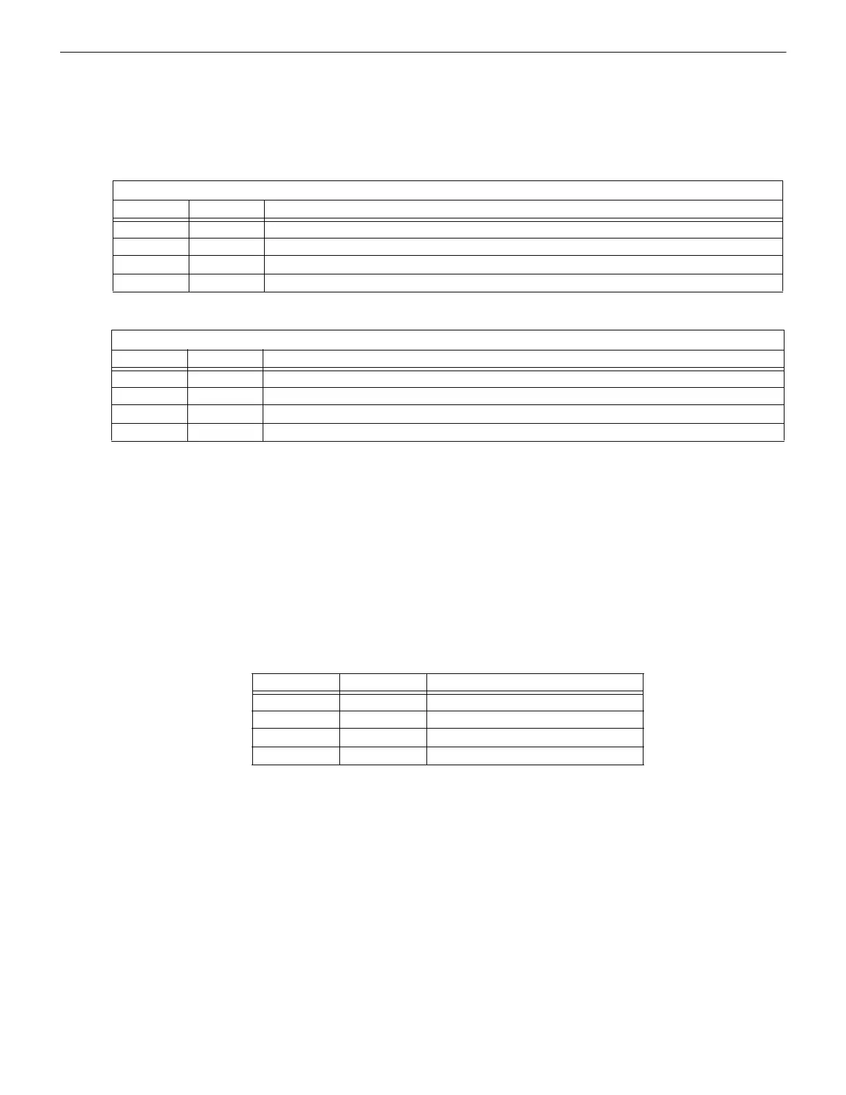
NAC Outputs 1 & 2
DIP Switch 1 DIP Switch 2 Function
OFF OFF Pass-through (Slave) (of Steady On, sync, or audible coded; DO NOT use with full-wave rectified input).
ON OFF Temporal generator.
OFF ON Sync generator (see Synchronization Type below).
ON ON Pass-through (Slave) Filtered (use for full-wave rectified inputs).
Table 3.2 Input/Output Configurations for NACs 1 & 2
NAC Outputs 3 & 4
DIP Switch 3 DIP Switch 4 Function
OFF OFF Pass-through (Slave) (of Steady On, sync, or audible coded; DO NOT use with full-wave rectified input).
ON OFF Temporal generator.
OFF ON Sync generator (see Synchronization Type below).
ON ON Pass-through (Slave) Filtered (use for full-wave rectified inputs).
Table 3.3 Input/Output Configurations for NACs 3 & 4
DIP Switch 5 DIP Switch 6 Synchronization Type
OFF OFF Cooper Wheelock devices
ON OFF System Sensor devices
OFF ON Amseco and Faraday devices
ON ON Gentex devices
Table 3.4 Synchronization Type for DIP Switches 5 and 6
 Loading...


