Installation Mounting Addressable Modules
22 HPFF8(E)/HPFF8CM(E) NAC Expander — P/N 53499:B4 10/1/2018
2.5 Mounting Addressable Modules
The HPFF8 and HPFF8E are designed to mount Honeywell Fire Systems addressable control or relay modules on the Control circuit
board inside the power supply cabinet. This allows power to be fed from the Auxiliary output directly to the module, if needed, without
running the power wires outside the cabinet. For a list of compatible optional modules that can be connected to the Auxiliary output,
refer to the HPP Device Compatibility Document. Two single-output modules may be mounted directly above each other if required by
applications such as Split Alarm or Selective Silence. Alternately, two outputs of a six-output addressable module can also be used and
mounted on the Control board.
TB3
TB4
TB1
TB2
SW2
LEDs
REF+ REF– + IN – IN
+ OUT
– IN
+ OUT+ OUT
+ IN
– OUT
SIGNAL 1
SIGNAL 2
BATT+ BATT–
A+
N/O
N/C COMM
N/O
N/C COMM
AC FAIL
TROUBLE
J1
J2
1L1 1L2 2L1 2L2
3L1 3L2
4L1 4L2A–
– +
– +
– + – +
F
F
8
1
2
_
3
1
0
7
6
.
w
m
f
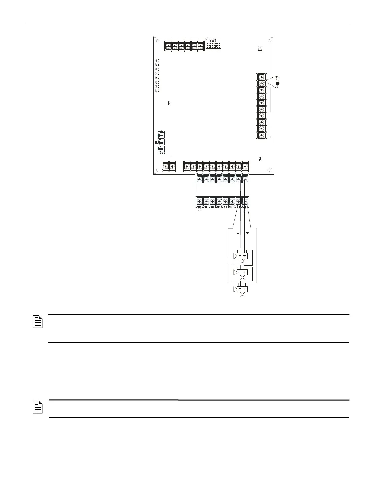
Reference Resistor
3.9KΩ is required for
the Class A adapter.
Alarm Polarity
Shown
• Trouble on NAC1 will illuminate
LED1 SIG1 TRBL
• Trouble on NAC2 will illuminate
LED2 SIG2 TRBL
• Trouble on NAC3 will illuminate
LED3 SIG3 TRBL
• Trouble on NAC4 will illuminate
LED4 SIG4 TRBL
Note: ELR is not required for
Class A wiring, but the 3.9KΩ
reference resistor is required.
NACs 1 - 3 are wired the same
as NAC4.
Note: Use wire gauge from
12AWG-18AWG.
}
NAC Out
}
NAC Return
}
}
}
}
NAC1 NAC2 NAC3 NAC4
Figure 2.13 Four Class A (Style Z) NACs with HPP31076 Adapter
NOTES:
1. Typical ELRs for new installations can be 3.9k or 4.7k ohm.
2. The same gauge wire must be used if two conductors are connected to the same terminal of any terminal block.
3. Do not complete a continuous circuit around the screw terminal. There must be two separate wires on either side of the screw at the
terminal block. “T-tapping” is absolutely NOT ALLOWED.
NOTE: An optional module mounting kit (P/N 90475) is required to install an addressable module on the Control circuit board. The kit
includes four male/female standoffs as well four mounting screws. The standoffs install directly onto pems that are factory installed in the
Control circuit board.
 Loading...


