36 HPFF8(E)/HPFF8CM(E) NAC Expander — P/N 53499:B4 10/1/2018
Applications Controlling and Silencing Four NACs
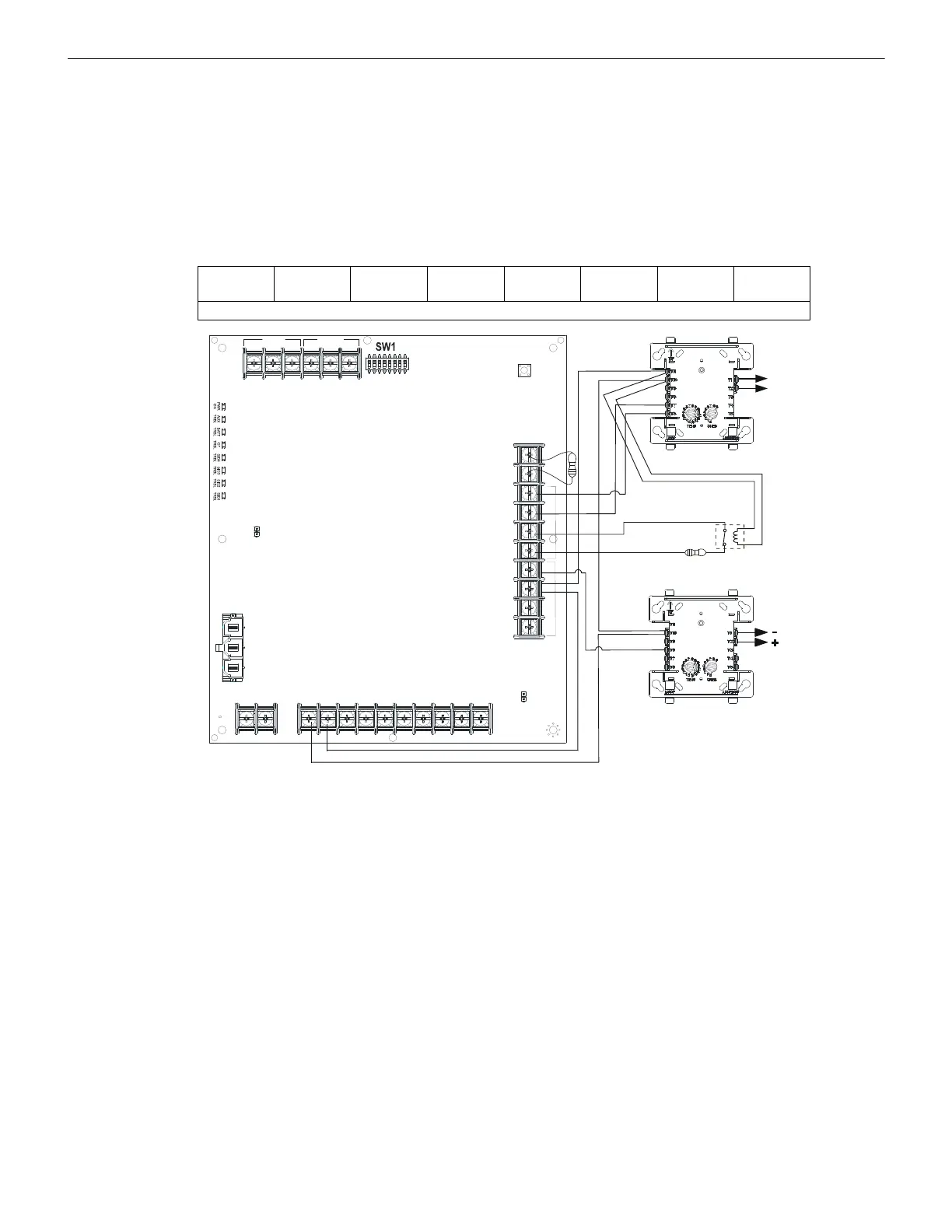
5.2 Controlling and Silencing Four NACs
In this application, the power supply has been set as a master with synchronized, silenceable outputs (see SW1 switch settings in follow-
ing illustration). The four NAC (Notification Appliance Circuits) output circuits can be silenced in the sync generation mode by remov-
ing alarm input from Signal Input 2. This can be accomplished using two addressable modules as illustrated in Figure 5.2.
The FACP must be capable of a visual annunciation to the silencing status of the output or zone(s) to which the HPFF unit(s) are con-
nected. The addressable modules are shown to demonstrate the use of a remotely mounted device associated with an addressable fire
alarm control panel. The module could be replaced with any circuit capable of polarity reversal, such as an FACP NAC.
Two independent inputs are required for silencing. Two separate addressable modules can be used as shown in Figure 5.2, mounted on
the control board (one on the other) or in a separate UL-Listed panel. Alternately, two outputs of a six-output addressable module can
also be used and mounted on the Control board (see Section 5.3, “Split Alarm and Selective Silence”).
Notes for Figure 5.2:
1. When the power supply is in normal/standby state, a trouble will result in an open circuit condition on the control module output
circuit (monitored by the End-of-Line Resistor on TB3). The HPFF's alarm input circuit will always remain closed in the alarm
state. Therefore, the Trouble contacts at TB2 need to be used to report troubles to the FACP during an alarm. Refer to Section 4.1 on
page 31.
2. The addressable relay module must be programmed as a silenceable point at the FACP to allow silencing of horn/strobe devices.
3. The addressable control module must be programmed as a non-silenceable point at the FACP.
4. Do not loop wires under screw terminals. Break wires to maintain proper supervision.
5. The value of the ELR (End-of-Line Resistor) across TB3 terminals depends on the control module used.
6. For a list of compatible devices, refer to the
HPP Device Compatibility Document.
7. The same gauge wire must be used if two conductors are connected to the same terminal of any terminal block.
8. Do not complete a continuous circuit around the screw terminal. There must be two separate wires on either side of the screw at the
terminal block. “T-tapping” is absolutely NOT ALLOWED.
SW1-8
OFF
SW1-7
NA
SW1-6
OFF
SW1-5
ON
SW1-4
ON
SW1-3
OFF
SW1-2
ON
SW1-1
OFF
All four NAC outputs will have silenceable sync for System Sensor devices.
TB3
TB4TB1
TB2
SW2
LEDs
REF+ REF– + IN – IN
+ OUT
– IN
+ OUT+ OUT
+ IN
– OUT
SIGNAL 1
SIGNAL 2
BATT+ BATT–
A+
N/O
N/C
COMM
N/O
N/C
COMM
AC FAIL
TROUBLE
J1
J2
1L1 1L2 2L1 2L2
3L1 3L2
4L1 4L2A–
FF8-4nacs-is.wmf
Control Module
Non-Silenceable Point
Activated by Alarm
Relay Module
Silenceable Point
Activated by Alarm
Alarm Polarity
Shown
Supervision
Relay
SLC
SLC
ELR
Figure 5.2 Controlling and Silencing Four NACs
Pwr-
Pwr+
A/B-
A/B+
Ref +
Ref -
In #1 +
In #1 -
Out #1 +
Out #1 -
In #2 +
In #2 -
Out #2 +
Out #2 -
 Loading...


