PSE Series Instruction Manual — P/N LS10227-000NF-E:B 3/29/2021 13
NAC Circuit Wiring Installation
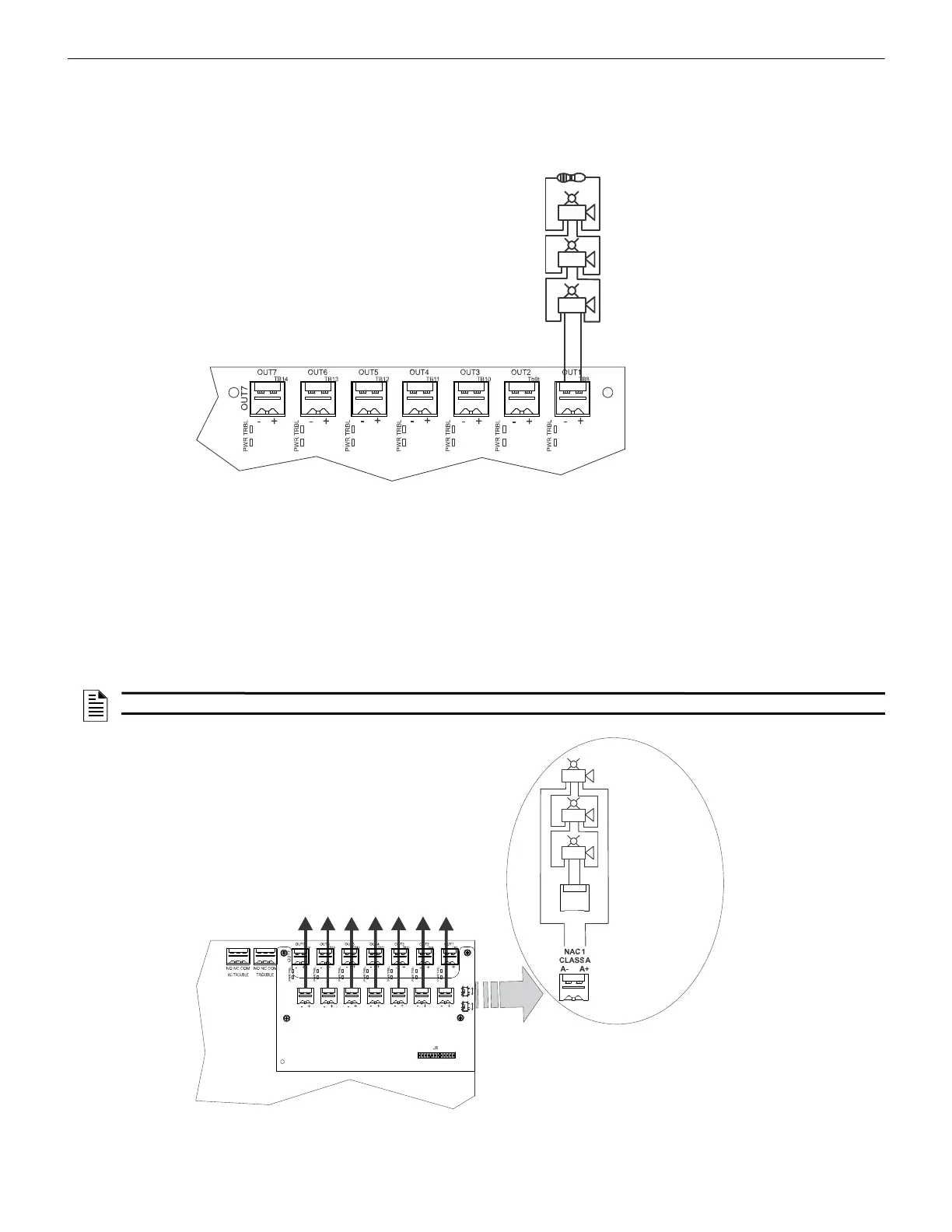
2.2 NAC Circuit Wiring
2.2.1 Class B
The standard configuration for NACs is Class B as shown below. Use Listed ELRs supplied by the FACP or compatible equipment man-
ufacturer.
2.2.2 ZNAC-PS Class A Option Module
The ZNAC-PS is an optional Class A conversion module which mounts to connector J8 on the upper right side of the circuit board. This
module allows the PSE-6 or PSE-10 to support Class A Notification Appliance Circuits on all outputs. Class A power supervision is also
supported on output circuits #1 and #2 when either of these outputs are configured as resettable or non-resettable Auxiliary power.
Two slide switches are located on the right side of the ZNAC-PS module to properly configure output circuits #1 and #2 for either NAC
or Auxiliary Power operation, as described below. Note that there are no slide switches for the remaining outputs as these outputs do not
support Class A power supervision.
• For output #1, set the upper switch to either “NAC1” or “AUX1” depending on the intended operation.
• For output #2, set the lower switch to either “NAC2” or “AUX2” depending on the intended operation.
Figure 2.2 NAC Class B
2k-27kΩ ELR
Horn Strobe
Horn Strobe
Horn Strobe
Alarm Polarity Shown
PSE Circuit Board
NOTE: Class A supervision and the ZNAC-PS module are not intended for use with door holder operation.
+
-
+
-
+
-
NAC1
AUX1
NAC2
AUX2
T
B
2
T
B
1
O
U
T
6
O
U
T
5
O
U
T
4
O
U
T
3
O
U
T
2
O
U
T
1
Figure 2.3 Class A NACs using ZNAC-PS Option Module
ZNAC-PS Option Module
Horn Strobes
ZNAC-PS
Alarm
Polarity
Shown
PSE Circuit Board
 Loading...


