44 PSE Series Instruction Manual — P/N LS10227-000NF-E:B 3/29/2021
Application Examples Canada Two-Stage Application Using XP6-C
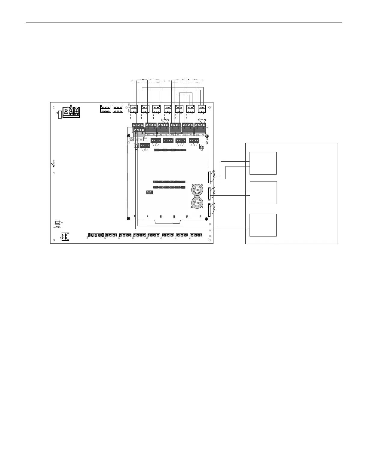
B.8 Canada Two-Stage Application Using XP6-C
In this application, two outputs are being controlled by an XP6-C multi-module inside the cabinet. NAC1 from the host FACP is provid-
ing the Canada two-stage audible pattern to the PSE. NAC2 is providing master sync or a steady output, depending on its capabilities.
Additional PSE outputs can be used to connect to XP6-C modules outside the cabinet.
The following notes apply to Figure B.8.
• PSE Output #1 is programmed to activate on Command Input #1 and Slave Mode (NAC Follower).
• PSE Output #2 is programmed depending on host FACP capabilities:
– FACP NAC2 provides master sync: PSE output #2 activate on Command Input 2, slave mode (NAC follower)
– FACP NAC2 provides steady output: PSE output #2 activate Command Input 2, master mode (select appropriate strobe
manufacturer)
• Jumpers must be installed on terminals T11, T12, T14, and T15 of the XP6-C module.
• Unused control module NAC outputs need ELRs installed or must be disabled.
• PSE outputs going to XP6-C need ELRs installed.
• Due to the reverse-polarity supervision of the PSE outputs, the XP6-C points must have the type code, “Bell Circuit”, to prevent
“Ext Power Loss” troubles.
NO NC C NO NC C
TB4
TB15
T
B
2
T
B
1
T
B
1
3
O
U
T
6
T
B
1
2
O
U
T
5
T
B
1
1
O
U
T
4
T
B
1
0
O
U
T
3
T
B
9
O
U
T
2
T
B
8
O
U
T
1
–
+
–
+
–
+
–
+
–
+
–
+
–
+
–
+
–
+
–
+
–
+
–
+
T
1
0
J
1
B
A
S
E
A
D
D
R
E
S
S
+
0
B
A
S
E
A
D
D
R
E
S
S
+
1
B
A
S
E
A
D
D
R
E
S
S
+
2
B
A
S
E
A
D
D
R
E
S
S
+
3
B
A
S
E
A
D
D
R
E
S
S
+
4
B
A
S
E
A
D
D
R
E
S
S
+
5
S
W
1
T
1
+
1
+
0
+
2
+
3
+
4
+
5
T
0
T
2
T
3
T
4
T
5
T
1
1
T
1
2
T
1
3
T
1
4
T
1
5
T
1
6
0
1
2
3
4
5
6
7
8
9
1
0
1
1
1
3
1
4
1
5
1
2
0
1
2
3
4
5
6
7
8
9
T0, T1, T2
visual appliance circuits
T3, T4, T5
audible appliance circuits
NAC1
NAC2
SLC
Host FACP
Figure B.8 Canadian Two-Stage Wiring Using an XP6-C
 Loading...


