26 PSE Series Instruction Manual — P/N LS10227-000NF-E:B 3/29/2021
Programming Options Output Circuit Control DIP Switch Settings
Unused Outputs
The factory default setting for all output circuits is “unused/unsupervised” where positions 3, 4, 5, and 6 are set to the OFF position. Any
unused or disabled outputs in the system configuration must be set to OFF as shown below.
Remote Supply with Resettable and Non-resettable Power
Each output circuit on the PSE can be used as a remote stand-alone power supply to provide power to any devices that require filtered,
resettable or non-resettable power. The PSE can provide up to 3 amps of continuous current. Non-resettable power is suitable for power-
ing annunciators and other peripheral equipment. Resettable power is suitable for four-wire smoke detectors. Resettable outputs reset
when the mapped input receives a negative pulse trigger signal from FACP or control module. There will be a three second delay prior to
output reset. The output reset will last 10 seconds. Set DIP switches positions indicated in Table 3.10 below to select auxiliary power
type.
Door Holder
Each output circuit can be configured as a door holder circuit. Setting DIP switch positions according to Table 3.11 will configure the
selected output circuit as a door holder circuit which will provide a steady 24 VDC to door holders until a mapped input activates an
alarm or when an AC fail condition removes the power following a programmable delay. See “AC Loss Door Holder Dropout Timer” on
page 24 for more information.
Synchronization Mode - Master/Slave
The PSE power supply can be configured for Master or Slave Synchronization by setting DIP switches according to Table 3.12. Syn-
chronization is a feature that controls the activation of notification appliances in such a way that all devices will turn on and off at exactly
the same time. This is particularly critical when activating strobes which must be synchronized to avoid random activation and a poten-
tial hazard or confusion.
In some installations, it is necessary to synchronize the flash timing of all strobes in the system for ADA compliance. Strobes accomplish
this by monitoring very short timing pulses on the NAC power which are created by an FACP with synchronization capability. When
installed at the end of a NAC wire run, this power supply can track (follow) the strobe synchronization timing pulses on the existing
NAC wire run. This maintains the overall system flash timing of the additional strobes attached to this power supply. Note that strobe
synchronization works only with non-coded NACs.
When the output circuit is configured as a sync generator (Master Synchronization mode), the sync input circuit will only be used to trig-
ger the output. The power supply is the originator of the strobe synchronization pulse on the NAC output. Refer to Table 3.12 to select
the desired Master mode sync type.
When the output circuit is configured as a sync follower (Slave Synchronization mode), the power supply’s NAC outputs track the strobe
synchronization pulses present at the supply’s Input terminals (based on the settings selected from Table 3.8). The pulses originate from
an upstream FACP or other power supply. Some FACPs provide synchronization timing pulses from a dedicated sync output connector.
Connect the PSE input terminals to the FACP sync output connector instead of the FACP NAC.
If circuits are configured for both master and slave mode, devices must be installed in different zones or field of view on a circuit basis.
OFF ON NAC will activate when input #3 activates.
(Input #3 is only available on the PSE-10 model. If selected on PSE-6, this setting will default to
input #2.)
ON ON NAC will activate when any input (1, 2, or 3) activates.
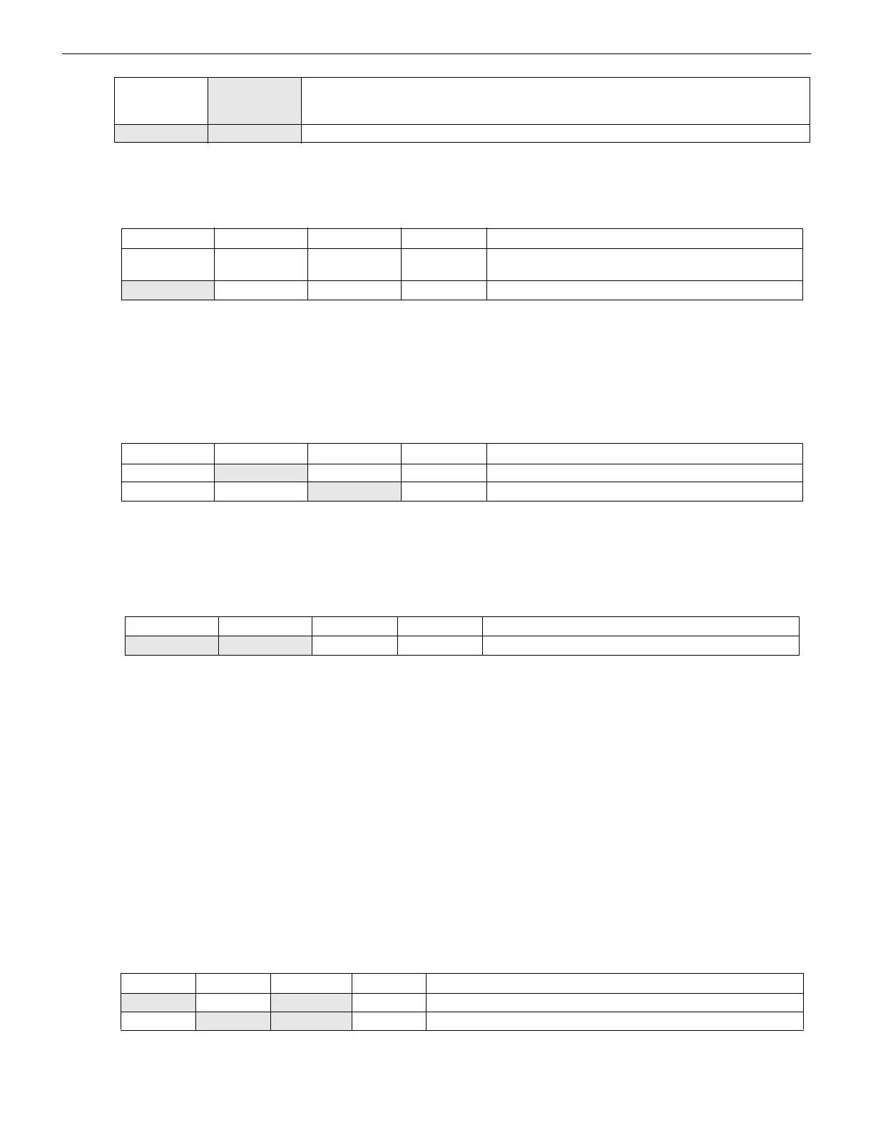
Position 3 Position 4 Position 5 Position 6 Auxiliary Power Type
OFF OFF OFF OFF Unused/Unsupervised. Outputs will not activate.
Factory default setting.
ON OFF OFF OFF Reserved- Outputs will not activate
Table 3.9 Auxiliary Power Settings
Position 3 Position 4 Position 5 Position 6 Auxiliary Power Type
OFF
ON OFF OFF Non-resettable (constant) aux power
OFF OFF
ON OFF Resettable aux power
Table 3.10 Auxiliary Power Settings
Position 3 Position 4 Position 5 Position 6 Door Holder
ON ON OFF OFF Set as door holder circuit
Table 3.11 Door Holder Power
Position 3 Position 4 Position 5 Position 6 Synchronization Type
ON OFF ON OFF Slave mode (NAC follower) - NAC outputs track Command Input Circuits
OFF
ON ON OFF Master mode - ANSI Temporal (Temporal 3)
Table 3.12 Sync Mode - Master/Slave Settings
Table 3.8 NAC Activation Settings
 Loading...


